| |
|
2/14/04 - 1 hour - Setup
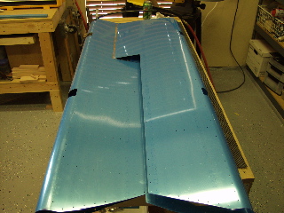
I removed the plastic from the inside of the elevator skins. |
 |
| |
|
2/15/04 - 1.5 hours - Stiffeners
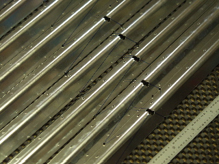
I removed the plastic from the stiffener material so I could mark on the metal. Next, I drew layout lines between the pre-drilled holes on the stiffener.
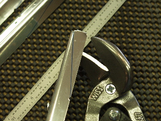
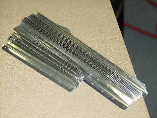
I used the tin snips to remove the unwanted material from the stiffeners.
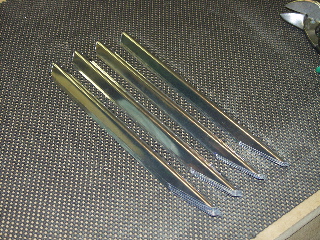
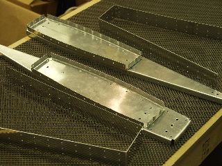
The result is a bunch of stiffeners which need to be deburred. |
|
| |
|
2/16/04 - 3 hours - Deburring, etc.
I finished manufacturing all of the E-908 and E-909 stiffeners. I used my belt sander once again to shape the corners of the stiffeners. For details, see the rudder page. I think it went quicker this time even though there were more of them. I finished shaping all of the stiffeners and then figured out that I had to cut nine of them to form the short stiffeners, so I wasted a bit of time doing that.
Next, I removed the protective plastic from the right elevator skin. This takes a while to do, so I only got one skin finished. I am trying to be careful not to cut scratches into the skins. |
|
| |
|
2/18/04 - Flight to Avery Tools
Although this is technically not a construction item, and therefore I didn't count the time as part of my build time, I have to make a note of the trip I flew to Avery Tools to do some tool shopping.
I flew to Hicks in Fort Worth, which is a small airport which is renowned for lots of RV building. The people at Avery Tools were really nice and helpful. I recommend them highly. They allowed me to return one item that was in my original purchase, even though it was about nine months ago.
I bought a 4" no-hole yoke for my rivet squeezer, as well as some other doodads.
Because of the fact that I was flying across DFW, and there's lots of air traffic to worry about, I took the opportunity to get flight following both coming and going. Although it required more radio work, it was really nice to have constant traffic alerts. On the return trip the controller vectored me right through Class Bravo airspace and directly over top of D/FW airport. I had done this once before during my night flying, but never had I done it alone and during a busy part of the day no less. It was cool. |
| |
|
2/22/04 - 5 hours - Match-Drilling & Deburring
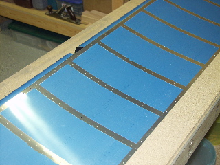
After messing with the rudder trailing edge debacle, match-drilling the elevator stiffeners to the skins was a nice change of pace.
The only tricky part with this is to make sure you mark the stiffeners so that later you get them back into the same location.
I deburred all of the holes on the skins and the stiffeners.
One thing that is unclear is how to deal with the platenuts. It appears that they need to be either dimpled or countersunk, but there is no mention of that in the instructions. It also seems that the material is too hard to dimple. I am going to check on the archives to see if this issue has been addressed. |
|
| |
|
2/23/04 - 2 hours - Dimpling & Countersinking
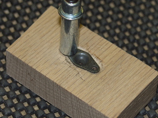
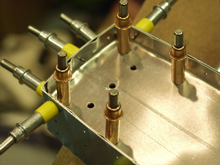
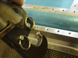
I spoke to a friend who is building a Sonex, and he recommended machine countersinking the platenuts (or is it nut plates.) So, I figured out a way to make a countersink into a block of wood that fits the #6 platenut so it sits flush with the top of the wood.
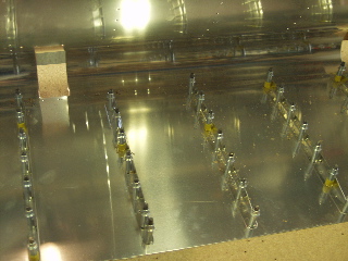
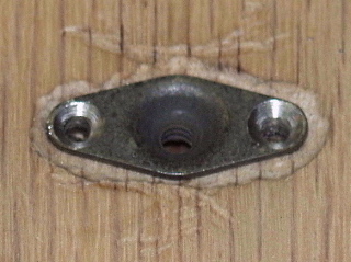
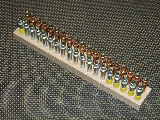
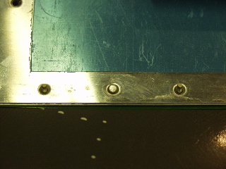
First I drilled one of the holes into the wood and attached a platenut with a cleco. Then I drilled the other holes and traced the outline of the platenut onto the wood. I used my Dremel tool to carve out the shape. Then I countersunk the center section to accept the dimple in the platenut. Finally, I clecoed each platenut to the wood block and used the micro-stop countersink cage in my drill press to do the countersinking. The results are great. You can see from the picture that the countersinks are nice and round. It was also fast.
These platenuts are intended for the little access door on the elevator for the trim tab control cable or servo. So I went ahead and countersunk the parts as is partially described in the plans. The plans say to dimple for the #6 screws, but there is no mention of the dimples for the platenut rivets. I assume this means that the builder is supposed to be smart enough to figure it out on his own. That's a big assumption in this case. So, I dimpled. I also dimpled the little cover piece.
I spent the rest of the evening dimpling the stiffeners and the skins. For some reason the instructions have me dimple the skins for the stiffeners, and then several steps later I will eventually dimple the skins for the spar and the tip ribs. Hopefully the reason will make sense. In the mean time it is quite a challenge to keep the skins open while using the c-frame to dimple. I put a piece of oak inside the skin to help hold it down, but I could really use a second set of hands to hold it open. Maybe tomorrow I'll find a helper.
Where are my kids...? |
|
| |
|
2/24/04 - 1 hour - More Dimpling
I had to stop dimpling the skins last night because the hammering was too loud. So, tonight I finished dimpling the skins for the stiffeners. |
| |
|
2/25/04 - 3 hours - Counterbalance ribs
These ribs turned out to be sort of tricky. They come out of the box sort of warped and bent, and I am supposed to flute the flanges until they match up nicely. Easier said than done. I started by laying each one on a flat table and fluting until they laid flat (sort of), then I clecoed them together and worked on getting the seam to disappear. After that, I added the skin and checked the prepunched holes to see how well I had done. Not very, I'm afraid. I had to do a bit of trial-and-error to finally get the holes in the skins and the holes in the ribs to match up. You can see in the first picture that I really had to flute the tip of the ribs to get them to match up.
Finally I was able to get the ribs and the skins to match closely enough, so I match-drilled them and then disassembled the parts for deburring/dimpling.
One thing that I was confused on until later was an irregular bump that is formed into both of the tip ribs. I looked at the plans but couldn't figure out why the flange would have these bulges in them. It was not until later that I discovered the reason: the inner rib fits underneath the spar flanges, and the combination of the two equals the thickness of the bulge in the tip rib.
One other interesting note. The instruction on the plan to "locally bevel" the counterweight skin in the appropriate places should not be ignored. It is pretty tight when all of these parts come together, and if the bevel is not there I don't think the ribs would fit into the skins correctly. |
|
| |
|
2/26/04 - 1.75 hours - Pre-assembly of Right Elevator
The plans say to go ahead and rivet the root rib to the spar with flush rivets at this time. I haven't primed yet, so I don't want to do that, so after looking at the plans, I decided that it would be okay to drill the control horn after I have completed the other steps. We shall see if it works.
Another item of interest is that they give you the option of using all cs4 blind rivets along the bottom of the spar, or using a combination of blind rivets and solid rivets in places where the spar can be reached with a squeezer. I decided to drill all of them to #30 and use pop rivets, because I can't see any benefit to using the solid rivets in this area other than the cost of the rivets.More on blind rivets
|
|
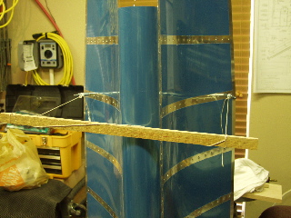
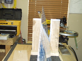
Remember earlier when I said that it was crazy trying to get the rib holes to line up with the counterbalance skins? Well, here we go again. The tip rib extends the length of the elevator skin, and the holes also need to match up. So, out come the fluting pliers again, and it's trial-and-error time for about 10 minutes or so until the holes seem to line up. The tricky part is that any change to the top flange also affects the bottom to some degree, so I found it easiest to set the elevator on end and adjust both sides at the same time until the holes on both sides lined up properly.
|
 |
I finally got everything together, so I match-drilled the ribs and the spar holes, and then I deburred all of the holes I just drilled out. The rivet holes along the bottom of the spar were drilled to #30 since they will be CS4 blind rivets. |
 |
| |
|
2/27/04 - 3 hours - Dimpling & Preparation for Priming
|
Did I mention I got a new pneumatic rivet squeezer? It's awesome with a capital 'A', baby. I used it to squeeze the dimples into the spar. Wow, it sure made easy work of that! I would really recommend one of these to anyone who is working alone.
The spar material is too thin to be countersunk, so I dimpled it, the same as the rudder spar.
I also dimpled the skin where the spar connects, and along the edges where the ribs will go. |
 |
| |
|
| I reassembled everything after dimpling just to be sure everything was ready to go, and guess what? I found a few spots that I had forgotten to dimple, namely along the root rib. |
|
| |
|
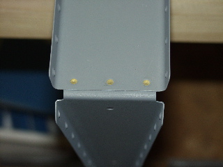
| Here's a picture of the root rib. Notice that I still haven't drilled the WD-605 control horn. I am waiting until primer is on. |
 |
| |
|
| And here is the tip rib and counterbalance clecoed into place.Everything is ready to go, so I took it all apart. Yippee. |
 |
| |
|
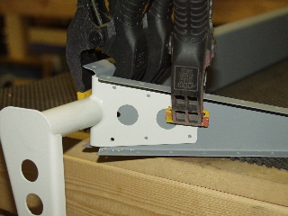
| Here I am using scotchbrite pads to scuff the parts in preparation for priming. This is a nasty job that is sure to introduce some sort of repetitive stress syndrome over time. Here I am wearing latex gloves just because I didn't want aluminum dust in my skin again. |
 |
| |
|
2/28/04 - 3 hours - Priming, assembly
Before priming I finished with the scotchbrite pads, and then I cleaned every piece with Acetone. Here is my solution for holding the skin open while I sprayed the primer. The skin is bent in such a way that it naturally is closed, and you have to hold it apart when working on the inside. So, I put clecoes in a hole in each side of the skin, and used some string and a stick to make something like a bow to hold the skin open.
There are no pictures of the priming process, but I did get a new respirator from Home Depot. It's much better than the little mask I was wearing before, and I could definitely tell a difference. |
 |
| |
|
| With the primer dry, I went ahead and riveted the root rib into place. It uses flush rivets so that the WD-605 control horn doesn't interfere with the rivets. |
 |
| |
|
| Now, finally, I can drill the WD-605. The instructions say to position it centered on the spar. They didn't provide any other reference points, so I did the best I could. I guess it is not totally critical, or they would have provided more specific instructions. |
 |
| |
|
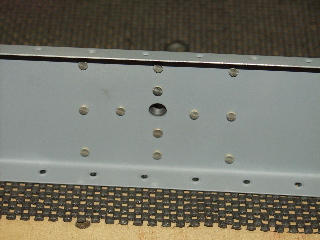
| Anyways, I drilled the holes to #30 and clecoed it into place. Looks centered to me. |
 |
| |
|
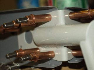
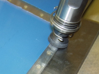
| Next, I used my fancy new squeezer to install the doubler plates and the platenuts on the back side of the spar. Sorry you can't really see the plate or the platenut, but you can see the totally perfect shop heads on those rivets thanks to my new pneumatic squeezer!!! |
 |
| |
|
2/29/04 - 2 hours - Assembly
The tip ribs were next. They have to be riveted together, and since I don't have a longeron yoke I had to use the rivet gun instead of the squeezer. Fortunately I was able to do a satisfactory job of riveting with the gun, although I can definitely see a longeron yoke in my future. |
 |
| |
|
| Next, the counterbalance skin is riveted to the ribs, starting at the tip and working aft, making sure to leave the last set of holes open so they can attach properly to the elevator skin. |
 |
| |
|
| All done. |
 |
| |
|
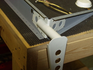
| The WD-605 control horn was attached next. |
 |
| |
|
| Done. |
 |
| |
|
I got tired of having to use two hands to put a cleco in the pliers, so I made a little stand so I can cleco small assemblies more easily. Neat, huh? Piece of oak, bunch of holes, cost: zero.
Oh yeah, one more thing: I decided to go with electric elevator trim. So, I will be installing the trim servo in the left elevator whenever it arrives. |
 |
| |
|
3/1/04 - 2.5 hours - Assembly
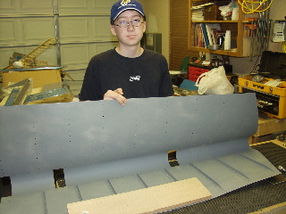
I had a willing helper (my son Tim) hold the skin open for me so I could back rivet the stiffeners in place. This was a great help, but when I started working on riveting the spar, that's when the help was really valuable. I had two of my sons helping. Jonny, who is 8 would put the rivet in the hole, Tim handled the rivet gun, and I did the bucking on the inside. It went very smoothly. I knew all these kids would come in handy. |
 |
| |
|
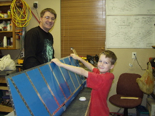
| Incidentally, I even had my wife out here helping for a little while. Maybe she was feeling left out of all the excitement. |
 |
| |
|
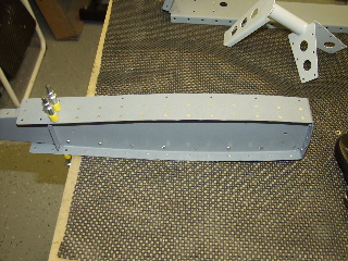
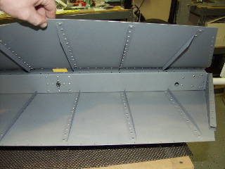
| After installing the stiffeners and the top of the spar, it looked like this. |
 |
| |
|
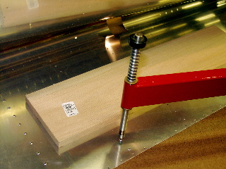
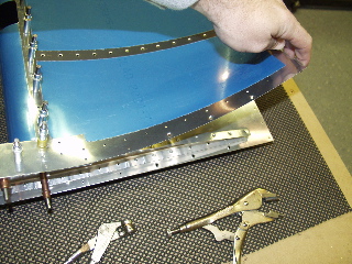
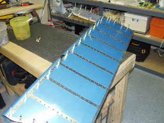
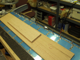
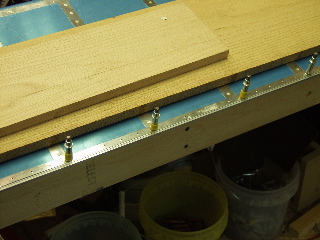
| The plans say to place the elevator on a flat surface and weigh it down before riveting the bottom skin to the spar. I used a couple of pieces of oak to provide uniform weight across the elevator. |
 |
| |
|
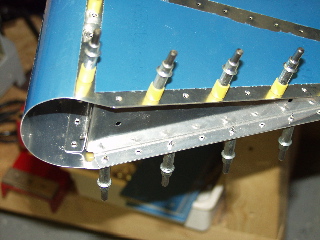
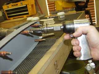
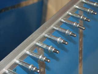
I used my pneumatic pop-rivet gun to install the blind rivets along the bottom of the spar.
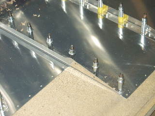
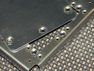
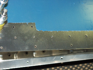
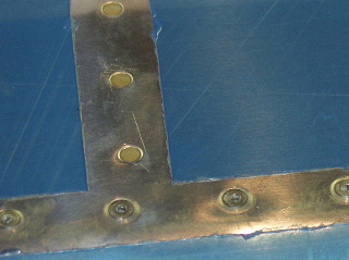
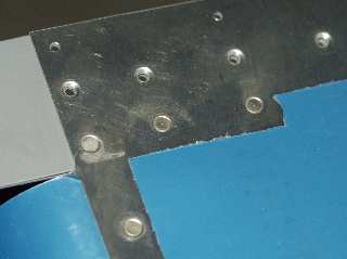
Here is a close-up of a line of blind rivets on the spar compared to the solid rivets on the stiffener. I think it looks just fine, and is definitely strong enough. Besides, it's on the bottom of the elevator. It will never be seen by anyone but me. |
 |
| |
|
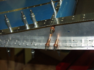
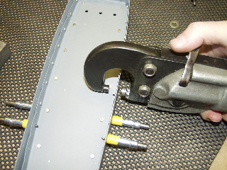
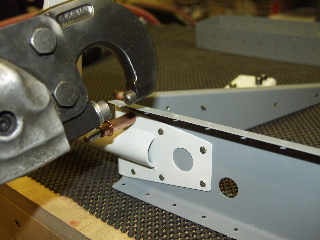
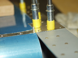
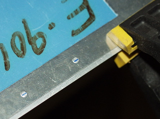
| Dilemma: how am I going to get this rivet squeezed/bucked? I think I am going to have to get creative. |
|
| |
|
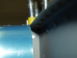
| That narrow space is all I have to work with. |
 |
| |
|
3/2./04 - 1.5 hours - Bucking Rivets
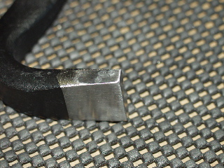
Well, I got it riveted. How did I do it? I took a trip to my local aviation store, Home Depot, and I bought a "Gorilla bar" crowbar. I cut off the forks from one end and polished the sides on the scotchbrite wheel. I was able to use this homemade bucking bar to reach into that narrow space and buck the back of the rivet. |
 |
| |
|
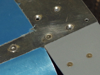
| This is what the end looks like after I was finished. |
 |
| |
|
| The other two rivets weren't so easy to reach either. They required that I reach inside the skins and buck them with a thin bar. |
 |
| |
|
3/4/04 - 4 hours - Trailing Edge
This was a rather confusing process. The plans say to draw a line 7/32 to 1/4" aft of the forward edge of the AEX wedge. The plans also specify that there would be about a 1/16 overhang that would need to be filed off. Well, when I did as it said I ended up with about 1/8" overhang. So I cheated it back just a bit until there was only about 3/32" overhang. This is probably not a big deal, but I kept going back and forth on it for about 30 minutes. |
 |
| |
|
| I drilled about every 10th hole. Then I went back and drilled the in-between holes. I drilled straight through the wedge and into the aluminum angle that I had attached underneath the trailing edge. |
 |
| |
|
| The plans say to drill perpendicular to the chord line of the elevator. fortunately they show how you can make a little template, so I cut one out of cardboard and laid it next to my drill for each hole.
With the trailing edge fully drilled, and with the angle attached, it looked like this.
One warning to anyone else who does this. When I followed the plans and let the trailing edge overhang the edge of the bench while drilling, I introduced a very slight bend in the skins due to the weight of the angle. I recommend supporting the angle in some way so the elevator doesn't have to.
|
 |
| |
|
3/5/04 - 1 hour - Trailing Edge
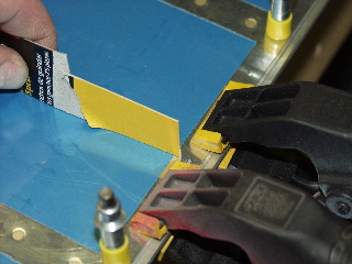
I went to the local feed and seed store and bought a couple of syringes without needles in them. I used one of these to apply the T88 epoxy to the trailing edge. I had to remove the primer from the edge because I forgot to mask it before priming.
I will let it dry for a few days before I rivet. |
 |
| |
|
3/12/04 - 2 hours - Trailing Edge
The glue is dry. I gave it a good long time to set up, but it is time to finish it. I removed all the clecoes and everything looks much better than my first try on the rudder. |
 |
| |
|
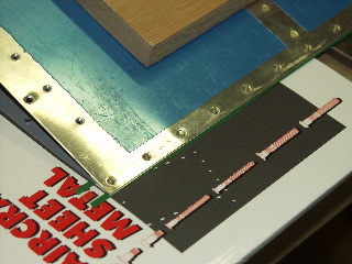
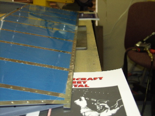
| I started by very carefully making sure that I had a flat surface around my back-rivet plate. I knew this Aircraft Sheet Metal book would come in handy sooner or later! |
 |
| |
|
Very carefully I set the rivets half way. This time I decided that it was unnecessary to alternate rivet directions, so I put the machined head on top of the rudder. I set every 10 rivets or so, and then went back and did every 5th, etc. until everything was riveted.
The funny thing is that the instructions tell you to check constantly to make sure it doesn't start to hook, but it doesn't tell you what to do if you notice anything. Fortunately it stayed pretty straight. |
 |
| |
|
| After using the back rivet set, I turned the elevator over and used the flush set to "set" the rivet to it's final size. I definitely did not overdo it, because I really beat up the trailing edge on my first rudder. |
 |
| |
|
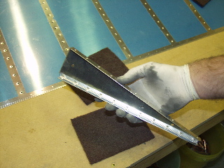
| The last thing I did was to use the file to clean up the trailing edge. The file that came with my Avery kit was very aggressive. I was surprised at the amount of metal it would remove. |
 |
| |
|
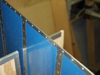
| Pretty straight. I am happy. |
 |
| |
|
| Done with the right elevator. Well, not totally done. I eventually have to do the counterweights and the fiberglass, but I will wait until later on those. |
 |
| |
|
| Next: Left Elevator |
|