| |
|
Last week marked the one year anniversary of the start of my RV-9A. I had about five months where I wasn't able to work on it due to our move to a new home, but I am moving ahead full steam now, so hopefully by next year this time I will be finishing up!
I also received notice from Vans that my Fuselage kit will be delivered the week of August 2nd. What could be better: come back from Oshkosh to a box full of airplane goodies! |
| |
|
6/21/04 - Plumbing - 2.5 hours
Before I complete the sealing of the inboard and outboard ribs I needed to complete the various and sundry plumbing and sensor details that have yet to be addressed.
The first item was to drill for the vent attachment. The position doesn't seem to be critical except that it can't interfere with the other items on the inboard rib. |
 |
| |
|
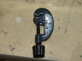
| I bought a cheap tubing cutter at Home Depot so I can properly cut the aluminum tubing. One thing I need to figure out is whether or not I am supposed to put a flare on the end of the tubing. The instructions are very weak in this area, so I may have to dig through the archives or even call Van's. |
 |
| |
|
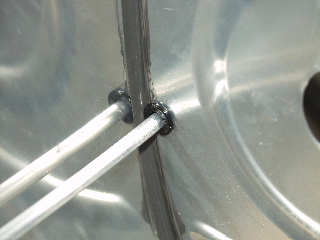
| The snap bushings snap into place and then the vent line feeds right through. I am wondering if I need to put some sealant on the snap bushing to keep it from moving around or, worse yet, coming out. |
 |
| |
|
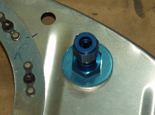
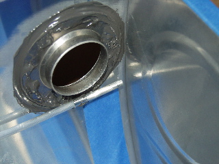
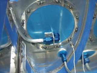
| Here is the vent line and the capacitive sender wire test-fit in the tank. The BNC connector comes with a little flat washer that has an electrical connection point on one side. I wonder if I should use it as-is or try to find a lock washer. I will be sealing it with ProSeal, so it may not make a difference. |
 |
| |
|
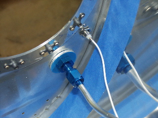
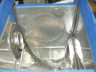
| Here is the vent line on the outboard end. It fits nicely into the clip. The only issue I can imagine is making sure it isn't too close to the outboard rib. I am going to leave mine about 1/4" from the outboard rib. That should be close enough to the top of the tank while providing enough space to keep small floating junk from clogging the vent. |
 |
| |
|
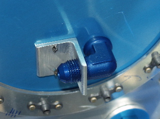
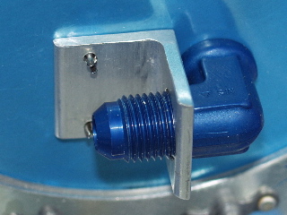
| Finally, I fabricated the anti-rotation brackets to hold the fuel pick-up tube in place. Upon first assembly it appears to be too low. Although I fabricated these exactly according to the plans, there are still threads on the other side of the bracket. I am concerned that I may need these for a good tight fit, so I may have to adjust the rivet holes. |
 |
| |
|
6/22/04 - Plumbing - 3 hours
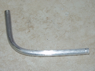
I started by fabricating the fuel pickup tube. This seems like a fairly important task that is barely mentioned in the instructions. I looked around on the web to see if I could find some examples to follow, but I didn't really find any. I finally went and re-watched the Orndorff video and sort of followed his example, although he didn't show much detail either. I bent the tube using a spring-type tubing bender from Home Depot. Once I had the shape about what I needed, I cut it to length a little longer than I thought I needed. |
 |
| |
|
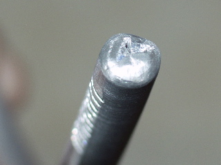
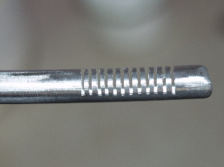
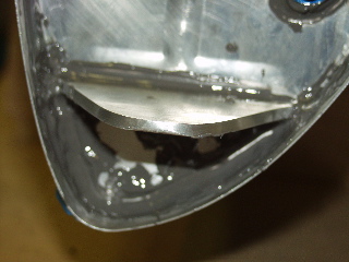
| The end needs to be closed up to force the fuel to be pulled through the screen. I did this by cutting a set of Vs in the end using my hacksaw, and then carefully peening it closed with a hammer and a punch. The results turned out pretty good I think. |
 |
| |
|
Here is my "screen." It is a series of cuts made by a hacksaw on one end of the pickup tube. This is low-tech, but it is simple and should work. I was happy to be able to cut the slots roughly parallel to each-other with nothing but a bench vise and a hacksaw. I used the side of the vise as a reference when making each cut.
I made two of these. |
 |
| |
|
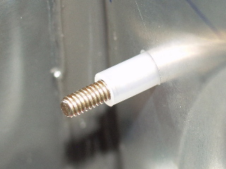
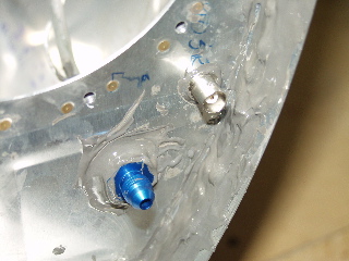
| The capacitive fuel senders are electrically insulated from the tank using a combination of sleeves and bushings. Here you can see how the bolt is insulated using a small length of tubing. |
 |
| |
|
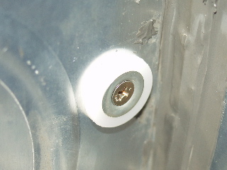
| This is what the back side of the bolt looks like. There is a washer and then a bushing keeping the metal from touching the tank rib. |
 |
| |
|
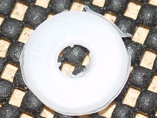
The funny thing about the bushings is that they are stamped out of teflon or something, and they have lots of "residue" on the sides from the stamping process. Since I just went to great lengths to create a filter for debris in the tanks, I wasn't about to install something with a potential to create debris, so I spent some time trimming the bushings with a sharp knife.
I felt sort of like I was building a plastic model. There are 48 of these bushings to trim. |
 |
| |
|
Finally back to the anti-rotation bracket. After discussing this with another builder I decided just to make new ones. Vans gives you a 2" piece of angle to make two 1" brackets. The cutting process uses about 1/8" of the material, so the best you can hope for is 15/16" for each bracket. This gives you very little room for error. In my opinion they should give you a 3" piece.
Fortunately, a friend locally had some 6061-T6 aluminum angle of the correct size, and he even cut two 1" pieces using his bandsaw. I remade the bracket, but I drilled the rivet holes "in assembly" to make sure it was correct. I am much happier with these. |
 |
| |
|
6/23/04 - Plumbing - 4 hours
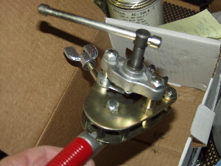
I received my Parker Rolo-Flair flaring tool from Avery today. I was able to use it to flare the tubing for both the fuel pick up tubes as well as the vent lines.
The first flare I made looked a bit strange, so I did another one. It too was weird but I couldn't figure out why. I then remembered that one of the selling points of this flaring tool was that it flared both the inside and the outside of the tube. My tubes were flared on the inside, but squared on the outside. I realized then that the flaring tool had been assembled BACKWARDS! The dies with the bevel were on the wrong end. So, I called Avery and they said Bob had left for the day. So, being the impatient person that I am, I decided that I could probably take it apart and fix it easier than having them ship me another one.
This was a great idea except that the little die wheels have little spring-loaded ball bearings in them, and when the die wheels were removed, the bearings popped out and dropped to the floor. I did this twice! So, I spent about 45 minutes on my stomach looking for ball bearings and springs.
Now that I have the tool back together it really does make nice flares. You have to make sure and oil it before you make the flare, and then you have to clean the part of oil afterwards.
For the record, the tool was in a sealed box from Parker, and so it wasn't Avery's fault that it was built wrong, but I recommend looking at yours if you buy one to make sure the bevels are on the right side. |
 |
| |
|
| I permanently installed the capacitive fuel senders. I finished my long process of trimming the plastic bushings so they didn't have the residue from the stamping process. This took proabably an hour. I crimped and soldered the ring terminals onto the wires and attached them according to the plans. |
 |
| |
|
| Here is the final pre-assembly of the innermost rib on the right tank. Everything that needs to be hooked up should be in position and should be ready to go. |
 |
| |
|
6/24/04 - Outboard Ribs - 3 hours
I had to disassemble the capacitive senders from the ribs so that I could apply sealant to the attachment bolt as the instructions tell you to do. I put sealant in and around the ring terminals as well.
The outboard ribs came next. I was able to use my pneumatic squeezer on most of these rivets, which was a nice change of pace. I also sealed up the tooling hole.
You may notice from this picture that the vent line is pulled away from the outboard rib. This is due to the fact that I haven't sealed it in place yet, and with the inboard rib still loose I was able to save myself some headache by pulling the vent line away from the area which I was trying to apply ProSeal. I'm really starting to dislike ProSeal! |
 |
| |
|
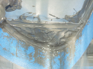
6/26/04 - Inboard Ribs etc. - 5 hours
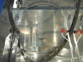
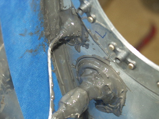
This is probably my worst picture so far, but it shows that I have installed the inboard ribs and the attachment brackets.
I really slopped on the ProSeal here. I have seen pictures of other builders' work who barely put any ProSeal, so I figure I am going waaaay overboard. If I have leaks I will be really surprised. Of course the tanks will hold about 10 gallons less of fuel! :-) |
 |
| |
|
 |
 |
| |
|
The tape will be removed and will show a nice clean line.
Next I will install the access plate with fuel pickup tube, and then I will do the rear baffle. Almost done! |
 |
| |
|
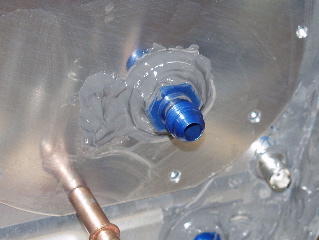
6/27/04 - Fuel Pick-up Tubes - 1 hour
The fuel pickup tubes and the anti-rotation brackets have been sealed to the access plates on both fuel tanks.
I also test-fit the plates to the tank with the seals in place, but I noticed that they may get in the way of riveting the baffle, so I removed them for the moment. |
 |
| |
|
6/28/04 - Right Tank Baffle - 5 hours
Well, I've stared at these tanks for long enough. I have cleaned them out and scuffed the ribs and the locations on the baffle where the ribs attach.
So, today I decided to do one of the tanks. I figure if I make any mistakes or if there are issues with the first tank not sealing properly that I can possibly make adjustments to the second one before sealing the baffle. |
 |
| |
|
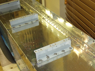
| The instructions say to put a cleco in every hole. There are a mess of holes to cleco. Once again, I probably used a bit more ProSeal than is necessary. I put some ProSeal into a 20cc syringe to apply the sealant to the sides of the tank. |
 |
| |
|
Once again I was very thankful to have the pneumatic squeezer. It made quick work of the rivets on the sides of the tank, and there are literally hundreds of them!
While clecoing the z-brackets I wondered if I should have placed sealant underneath the brackets. I didn't, so there is one possible place for leaks. We shall see...
I had to drill out only one rivet. This is a big mess with a ProSealed rivet because all the little aluminum shavings get stuck in the ProSeal. Yuck. |
 |
| |
|
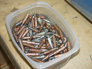
| Here's my bucket of dirty clecoes. I soaked them in MEK while I riveted, and then I spent about 1 1/2 hours cleaning them. Just think, I get to do all of this one more time in just a few days! |
 |
| |
|
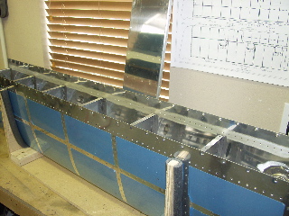
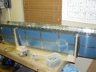
| So here is a picture of the right tank all done. Tomorrow I will install the access plate so I can see if there are any leaks. |
 |
| |
|
6/29/04 - Access Plate - 2 hours
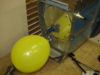
I installed the access plate and then I tried to figure out how I was going to pressure-test the tank. I decided to go with the balloon method because I thought it sounded more idiot-proof, which, at this point is a pretty important feature to me.
I had purchased the tank testing kit from Vans. It consists of a cap for the pickup line and a bicycle-type fill valve for the drain. This leaves the vent line open for the test. I put Duct Tape over the fill cap. |
 |
| |
|
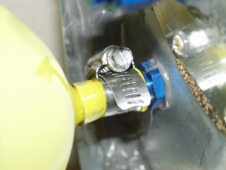
Initially I had some trouble getting the balloon itself to seal on the vent line. I tried wire, tape, and more wire and tape, but it continued to leak. What a pain.
My solution was to buy some 3/8" id plastic tubing, some 1/2" id plastic tubing, and a hose clamp. I put a 1" piece of the the 3/8" id tubing on the vent line, then I put the balloon over the tubing. Then I slipped a 1" piece of the 1/2" id tubing over the balloon. Finally I installed the hose clamp over the tubing and tightened it down. Bottom line, the tank does not leak! |
 |
| |
|
6/30/04 - Left Fuel Tank - 4 hours
I had some helpers today. We got everything ready for the left fuel tank. The z-brackets needed to be prepped, the baffle needed to be sanded, and the tank needed to be cleaned out in advance of being sealed up.
The extra help made the second tank seem to go much easier than the first. I enjoyed having someone else clean the ProSeal off the clecoes! |
 |
| |
|
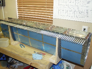
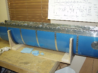
Here's the left tank all finished. I have already installed the access plate. Tomorrow I will pressure-test this tank.
|
 |
| |
|
| Next: Final Assembly |
|
| |
|