| |
|
Creativair Wingtip Lights
Initially I had planned on just using the Whelen Light Kit #7 from Van's catalog. The only problem is that it doesn't include landing lights. I didn't want to cut holes in the leading edge of the wings, and I had seen some nice wingtip landing lights at Oshkosh, so when I found the light kit that Bill Vondane sells, I was interested. This system uses high intensity LEDs for the left and right position lights. These draw very little current and are extremely visible. The landing/taxi lights are integrated into the assembly and use 75 watt halogen light bulbs. Strobes are powered by a single power supply. Best of all, the whole light solution fits under the standard wingtip light dome that comes standard on the -9A. The only other thing left to buy is the combo strobe/position light that fits on the bottom of the rudder. It's a very cool setup! I went ahead and ordered the kits a few months back so I would have the strobe power supply in-hand when planning the baggage compartment wiring. The kit is complete down to the rivets used to attach the nutplates. I think he sells these fully assembled as well, but I opted for the kit form to save some money.
You can visit CreativAir for details and online ordering. Bill has been very helpful with all of the questions I have had.
|
| |
|
2/2/05 - Shaping and cutting - 3 hours
I started with the position lights, thinking that I could do some soldering while it is so cold in the garage. Unfortunately there's some cutting to do before I can solder. I know you people up in the Great White North will laugh at me for saying that 40 degrees in the garage is too cold. Well, we don't have insulated garage doors down here and I don't have any type of heating unit out there, so leave me alone. Come down here in a few months when it's 100 degrees in the shade, and we'll talk. :-) |
 |
| |
|
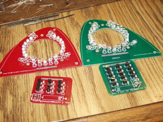
I started by cutting the circuit boards, separating the power supply section from the "display" section. I did this with an abrasive wheel in my Dremel tool.
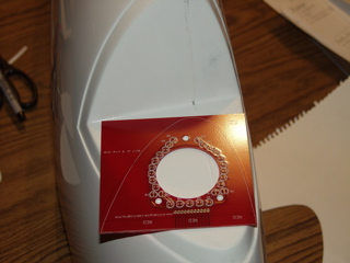
I made a paper template of the wingtip and transferred the shape to the circuit board. The board doesn't totally cover the surface area of the forward facing part of the wingtip, so I had to sort of shrink the shape an equal amount around the sides. |
 |
| |
|
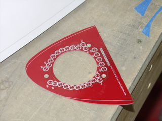
I cut the board to rough shape using a cutting wheel in my dremel tool. Then I tweaked the shape using a stationary sanding disc. By trial fitting it enough times I was able to get it pretty close.
Note: you're looking at the left side. The right side has a green board and is done the same way, only reversed. |
 |
| |
|
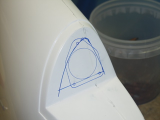
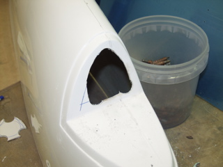
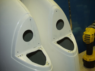
The instructions say to mark in 3/4" from the edges of the wingtip. This didn't really work for me, and you can see the difference between the 3/4" mark and the tracing of the landing light hardware. So, I used the shared outer dimensions of the two, and came up with a cutout area that would allow the landing light to be inserted easily.
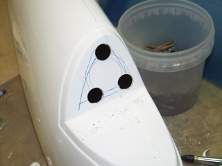
I used a 1" hole saw to drill the corners. Then I used the dremel tool to "connect the dots" and open up the hole. I used a drum sander in my cordless drill to clean up the edges of the hole. Expect to create lots of dust! |
 |
| |
|
 |
 |
| |
|
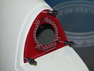
| With the hole cut out I was able to establish the best locations for the platenuts. I marked and drilled three screw holes into the circuit board, then I used the circuit board to match-drill the wingtip for #8 screws. |
 |
| |
|
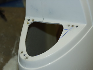
Next, I removed the board and mounted nutplates inside the wingtip. I used three different styles of nutplates. Also, the fiberglass varies in thickness, so each rivet had to be individually chosen for proper length.
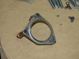
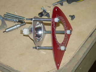
Before I started building the position lights I wanted to get a better idea of how the landing light goes together, so I preassembled the landing light components. I had to install the nutplates in one of the plates. Notice that in the picture I have not trimmed the springs or angled the bushings. This was just a trial fit. |
 |
| |
|
 |
 |
| |
|
| Okay, so I have established that the assembly will fit into the wingtip. Now I can start soldering. |
 |
| |
|
2/3/05 - Soldering - 2 hours
Time to solder the parts. I've had some experience working with small electronics projects, and I have a soldering station with a temperature controlled soldering iron, so this was pretty straightforward for me. One thing I would caution about is that when you solder tiny electronics parts you can't wait to see solder flowing into the joint. If you do that you've probably used too much solder. You have to practice touching the parts for as little time as is necessary to melt a tiny bit of solder into the connection. |
 |
| |
|
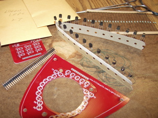
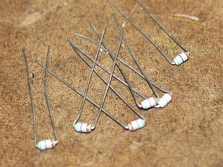
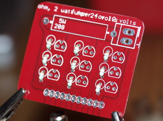
| First I installed the resistors onto the power supply boards (the small boards.) The holes on the board were spaced far enogh apart that I could install the small resistors flat against the board if I bent the leads close to the body of the resistor, so I did it assembly line style. I bent all the resistors, then I inserted them all into the board. The resistors aren't heat sensitive, so I was able to do all the soldering at once, saving some time and improving my soldering. |
 |
| |
|
 |
 |
| |
|
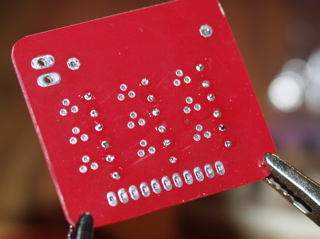
| The resistor leads were smaller than the drilled holes, so the solder tended to want to accumulate on the top side of the board rather than making a nice fillet around the lead at the bottom. No problem. As long as I have good solder joints I'm good to go. |
 |
| |
|
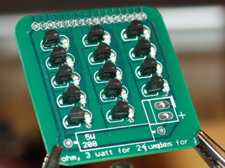
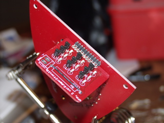
Next I installed the transistors on the power supply boards. For variety here is the green side. These can be damaged with too much heat, so I did these one at a time, letting the board cool between each one.
This is a tedius process so I stopped after the power supply boards were finished. Next I will install the LEDs. |
 |
| |
|
2/4/05 - Soldering, Strobes - 5 hours
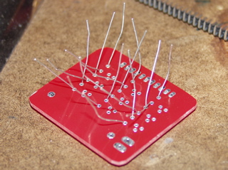
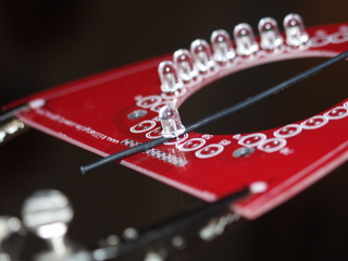
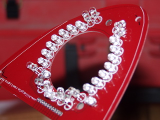
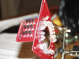
Next on the list is to install the LEDs on the boards. These need to be mounted at a specific angle to ensure adequate visibility from every angle.
The LEDs themselves are clear. You can't tell by looking at them whether they are red or green. So I did all of the red ones first before opening the envelope with the green ones. |
 |
| |
|
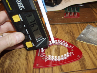
The angle of my wingtip was 24 degrees. So, according to the instructions I needed to angle the majority of the LEDs 14 degrees forward. I did this by first soldering the LEDs to the board using a piece of wire as a spacer.
I found an ink pin that I cut the tip off that fit the LEDs perfectly. I used this to do the bending.
I used my SmartTool to set the angle. LEDs which required a more significant angle I would pre-bend with needle nose pliers. |
 |
| |
|
 |
 |
| |
|
 |
 |
| |
|
The strobe lights will also go under the wingtip, but rather than mount them directly to the fiberglass I decided to attach them to an aluminum plate. These I made from some 6061 aluminum sheet, and I spent quite a while getting them shaped just right.
|
 |
| |
|
 |
 |
| |
|
2/5/05 - Finishing up - 5 hours
Next I had to solder the power supply board to the LED board using a header. I chose to have the header turn in towards the curved part of the LED board rather than towards the flat part because I thought it would make it easier to install the lights into the wingtips later on. I turned out to be right as this configuration just barely fits. |
 |
| |
|
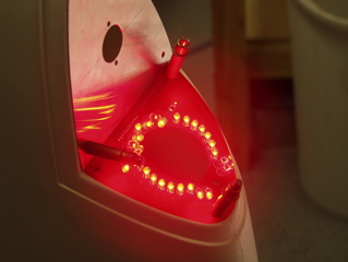
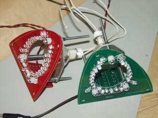
Here's a better picture.
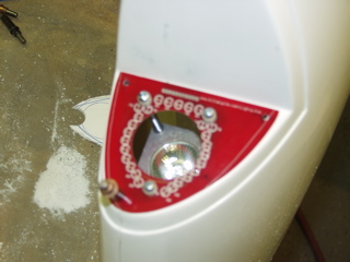
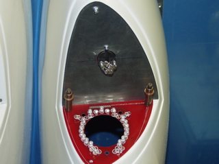
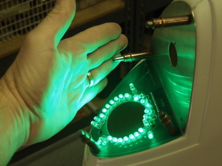
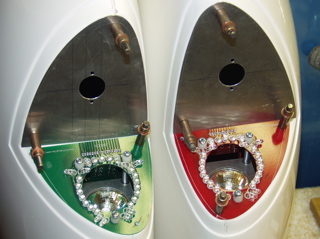
With everything soldered, it was time for a smoke test. So I temporarily installed them into the wingtips and attached some power. They are indeed bright. The pictures don't really do justice.
|
 |
| |
|
 |
 |
| |
|
| With everything tested out, I worked to install the landing lights. It took a while to experiment with the lengths of the springs. This is going to have to be adjusted once they are on the plane for good. |
 |
| |
|
| That's it. The lights are ready to go. Now I need to get the rest of the plane finished! |
 |
| |
|
Update:
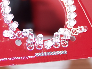
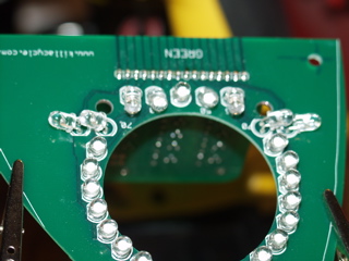
Bill Vondane emailed me to tell me that I had installed two of the LEDs facing the wrong direction. Rather than just bending the LEDs around, I desoldered the two and re-bent the leads and then reinstalled them.
You probably can't even figure out which two they are, can you? They are two of the ones marked 70° which face up and down when the light is in the plane. |
 |