| |
|
Previous: Engine Stuff 1 |
|
| |
|
8/26/05 - 8/28/05 - Misc. - 8 hours
Okay, it's really, really hot here. We've had a week or more of 103° temperatures, and there's not a lot of air movement, so my garage is like an oven. I have had to reduce my time out in the garage to avoid heat exhaustion. Naturally I'm drinking lots of water.
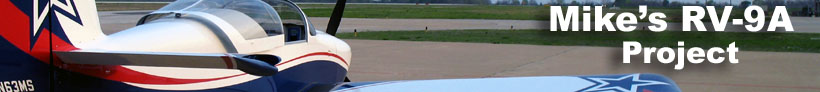
So, continuing down the list of things to do, the next item was to wire the capacitive fuel interfaces. These have longer coax cables which run out to the BNC connectors on the fuel tanks, and three short wires for connecting to power, ground, and one of the auxiliary inputs on the EIS. |
 |
| |
|
I added 3-conductor Mate-N-Lok connectors to the sensors just in case they need to be removed.
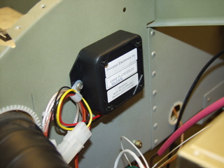
Next I added the alternator field wire. This goes from the back of the alternator to the voltage regulator inside the subpanel. The instructions from B&C say to connect the wire to both sides of the connector for redundancy purposes, which I did. I also used shrink tubing around the wires.
One thing I did Friday was to order a bunch of high temperature zip ties from SteinAir for use inside the firewall. The ones you see in the pictures will be replaced soon. |
 |
| |
|
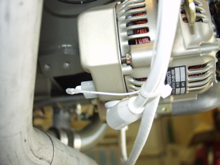
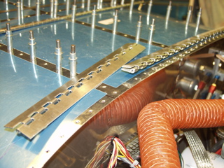
Next I started the process of assembling the filtered air box. I replaced the drain plug with the hex plug that was supplied by Van's. Then I had to cut the air filter and seal it up using red RTV. I used some paste wax on the carburetor as a release agent, and then I squirted RTV on everything. Once I had everything adequately covered, the instructions say to leave it to dry for 24 hours. Time to move on to something else on the list.
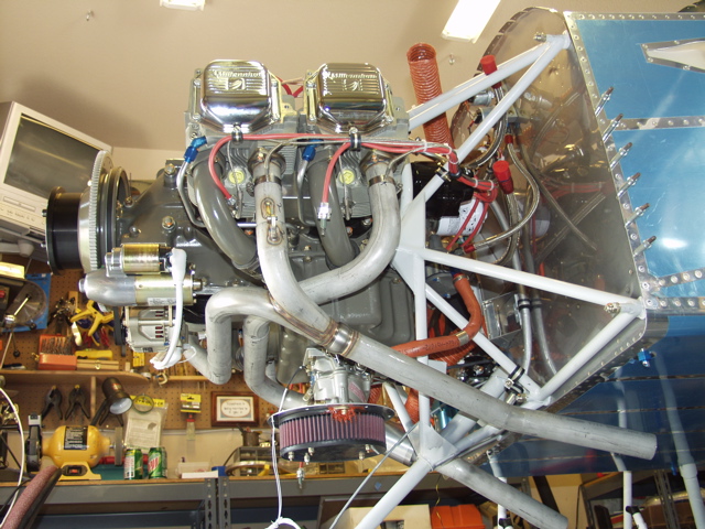
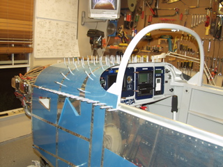
Here's a view from the bottom of the engine. From this you can get an idea of the status. |
 |
| |
|
 |
| |
|
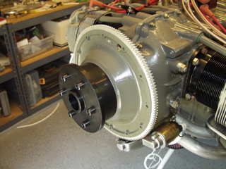
| I added the 2 1/4" extension to the front of the crankshaft. This is a brand new extension from Van's, and it is machined with extremely close tolerances. It fit like a glove. |
 |
| |
|
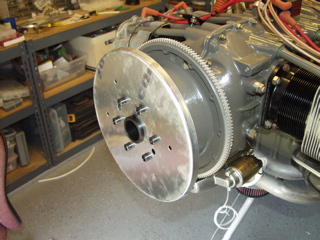
In order to anticipate the proper location for the cowl, I slid on the rear spinner plate. I don't have my propeller yet, but I can get a pretty good idea of where the front of the cowl should go. I really wish I had the prop in hand, but whatever.
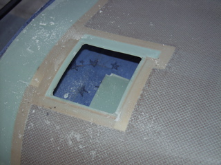
Before starting the cowl installation, the first thing I did was to take the manual inside and totally re-read the instructions and to study the plans in order to get a mental picture of the process. The first item was to cut the oil door opening. I did this by drilling four holes and then "connecting the dots" with my rotary cutter. |
 |
| |
|
 |
 |
| |
|
| Another easy task was to trim the forward parts of the cowl to allow some screw holes to be drilled into the sides of the cowl near the spinner opening. This is a little weird, since the exact geometry is not yet known, but I figure I can always go back and fill these holes and re-drill later. |
| |
|
 |
 |
| |
|
| I went ahead and temporarily reinstalled the forward top skin in anticiptation of the cowl installation. |
 |
| |
|
| Now it's time to attach hinge pieces. The plans are very vague about this process. |
 |
| |
|
8/31/05 - More Misc. - 4 hours
This stuff actually stretches over two evenings. I took the forward skin off once again to finish up the remaining items on my list. I want to make sure I have everything done up here before I permanently attach the top skin. So, I fiddled with wires and tubes and zip ties for a lot longer than I expected.
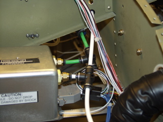
One item that I had been putting off was the attachment of the pitot and static lines to the two places behind the panel that require this connection: the EIS and the AHRS. |
 |
| |
|
It seems like forever ago that I bought this pitot-static tubing kit from SafeAir1. I had ordered it so I could do the static ports in the tailcone. Now it came time to attach everything else, so I dug through the supplies from the kit and came up with the required fittings.
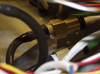
The hookups to the AHRS are extremely straightforward. The fittings simply screw into the AHRS and you're done. The EIS is a little more interesting, because I had to use the supplied black tygon tubing to go into the EIS, and then use an adapter to go from that tubing to the more substantial pitot and static lines. Here you can see the black tygon tubing as well as the fancy brass fittings. |
 |
| |
|
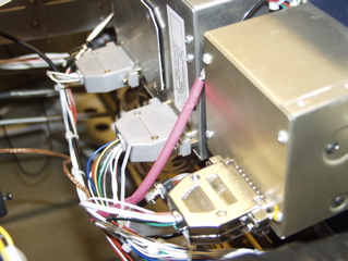
I also took the time to clean up the wires going to the EFIS and autopilot, and I attached the protective shells over the DB-25 connectors. I still haven't put any shells over the DB-9 connectors because the ones I have are only for the male side. I need to take a trip to Frys or Radio Shack and see what I can come up with.
If it seems like I'm not getting much acccomplished, it's because I'm waiting on my propeller. I decided that I really wanted the prop on the plane before I finalize the cowl position, so until I have the prop, I'm working on little piddly things. |
 |
| |
|
| One issue that I've been bothered by has been the routing of the pitot line. I have completely used up the space in the grommet that passes through the wing spar on the left side, so that is not an option. There is some space in the center section grommets, but this requires that I route the tubing near the stick control apparatus. I called Van's and talked to Gus about the possibility of drilling another hole, but we decided that it would be better to just route the line to the center grommet. He suggested bonding the tubing to the control bracket (the one that attaches to the spar and makes all routing very difficult) to keep it away from the controls. So that's what I did. I ran the line and then used RTV to "stick" the tubing to the left control bracket. |
| |
|
| Next: Finishing up the wings |
|
| |
|