| |
|
3/5/04 - 5 hours - Drilling & Dimpling
I had already done a bunch of the prep work when I did the right elevator. I had already made the stiffeners, drilled the skins, dimpled the skins and stiffeners, and prepared the counterbalance assembly.
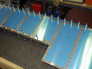
So, I started by clecoing together the skeleton and match-drilling the skins to the skeleton. |
 |
| |
|
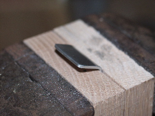
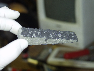
| The trim tab spar has to be countersunk in order for the hinge to be riveted to it. So, I used the piece of AEX wedge intended for the trailing edge to straighten it before I countersunk. It worked out well. |
 |
| |
|
| I put some soft rubber material inside the skin and then used the c-frame tool to dimple the skin where it attaches to the spar. This worked much better and did not cause as many "smiles" in the skin. |
 |
| |
|
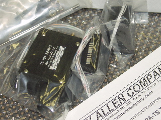
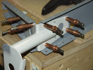
| Cool thing of the day: I got my trim servo. I wasn't quite sure what to expect in the package other than the servo, but I was pleasantly surprised to find that the package includes the servo, the hardware, the rocker switch, and the LED indicator. Here is a picture. |
 |
| |
|
| I made the gusset as described on the plans even though it's not even mentioned in the instructions. |
 |
| |
|
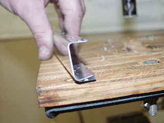
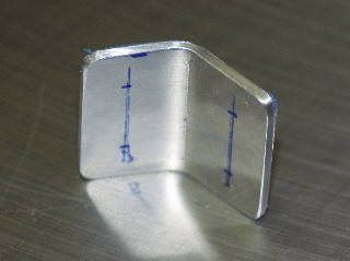
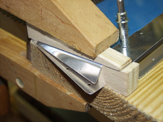
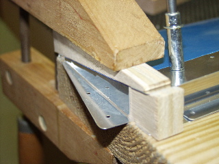
| It specifies a 68° bend. I clamped the piece in between two pieces of oak and whacked it with my dead blow hammer. I occasionally checked it against the skeleton where it would eventually fit. |
 |
| |
|
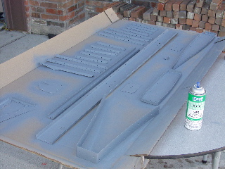
3/6/04 - 6.5 hours - Priming / Assembly
I spent a while scuffing and cleaning the metal, followed by some time outside with my gas mask on. I'm sure the neighbors think I'm from outer space or something. Anyways, the wind started picking up so I had to quickly move the dry pieces inside before they became airborne prematurely. |
 |
| |
|
| Next, I began assembly. Here is the back side of the spar showing the doubler plate and the nutplate. |
 |
| |
|
| Yes, I did remember to mask the trailing edges this time, so I won't have to sand off the primer later. Maybe I'm learning... |
 |
| |
|
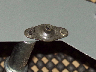
The control horn went on next.
Note: You can see in this picture that the powder coat had chipped off from the control horn, so I hit it with some primer. |
 |
| |
|
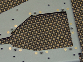
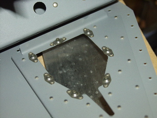
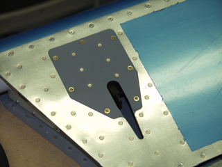
| Here's something sort of cool: I installed the nutplates around the trim-tab doubler plate. This is what it looks like on the top side. |
 |
| |
|
| And this is the bottom side. |
 |
| |
|
| Top side... |
 |
| |
|
| ...bottom side. |
 |
| |
|
3/12/04 -2.5 hours - Assembly
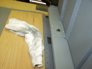
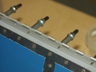
The top rivets to the spar are riveted by holding the skin open and reaching under the spar with a bucking bar. I used a rag to keep from scratching the primer. |
 |
| |
|
| Here's the other side. Notice the nice, organized row of clecoes, evenly spaced every other hole. That's because I'm strange. I had to remove the clecoes on either side of the current rivet or else my bucking bar would not fit. |
 |
| |
|
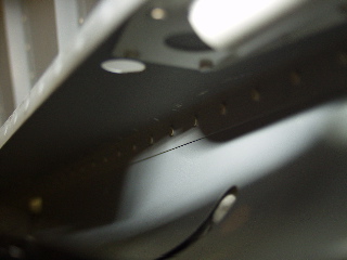
| Here's a bad picture of the rivets after I finished. |
 |
| |
|
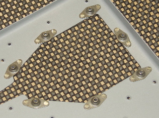
| Remember the trim doubler? Here it is installed. |
 |
| |
|
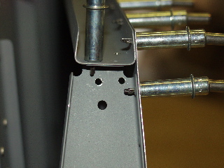
Boo-boo of the day: I drilled through the gusset and came out too close to the edge of the rib. It's supposed to be at least 1 1/2 times the width of the hole, but it's more like half the width of the hole. This plane is going to fall apart.
Actually, I did a bonehead thing. The plans say to drill the gusset in assembly. So, like a doofus, I went inside the elevator and drilled out through the gusset. In hindsight, I should have drilled through the rib and into the gusset. Live and learn. |
 |
| |
|
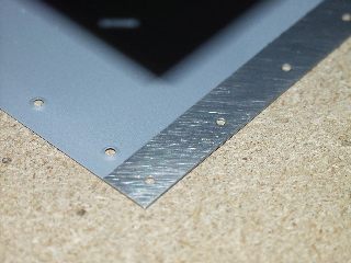
3/13/04 - 6 hours - Trailing Edge
This is sort of a repeat of the right elevator, except that I learned a few things doing the right one and I wanted to show my improved method.
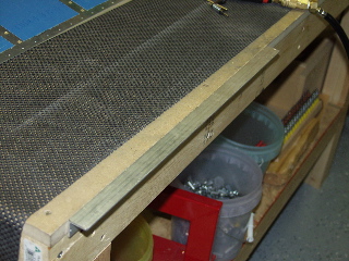
I attached the aluminum angle directly to the side of my workbench with a couple of screws, making sure it was totally flush with the top. |
 |
| |
|
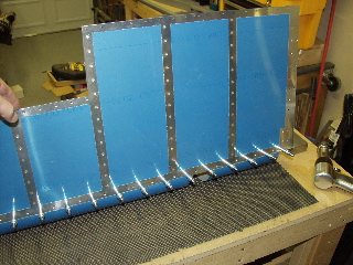
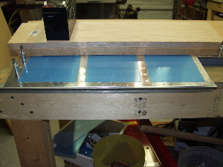
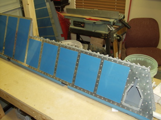
| Next, I laid the elevator on the workbench with the trailing edge resting over the aluminum angle, and weighed down the elevator with wood and whatever other junk I had laying around the shop. That black thing is a battery I found on the street the other day. So what, it's heavy. |
 |
| |
|
My process of drilling was the same, except that I would put my clamps on either side of the hole I was drilling, which helped keep the skins from separating and making a mess.
Other than that, the trailing edge is now epoxied. In a few days I will finish this up. |
 |
| |
|
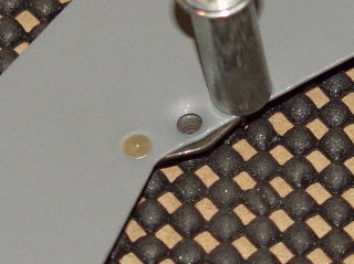
4/4/04 - 2 hours - Trim Tab
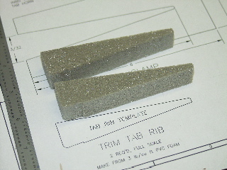
I formed the little foam ribs using my scrollsaw and a piece of sandpaper on a flat surface. I also masked out the spaces which will eventually have ProSeal attaching the rib to the skin. |
 |
| |
|
4/5/04 - 2 hours - Trim Tab
I match-drilled the spar to the skin. I also cut the control horns down per the plans for using the electric trim. The order of construction in the instruction manual is somewhat suspect, but I tried to follow as closely as possible. |
 |
| |
|
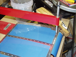
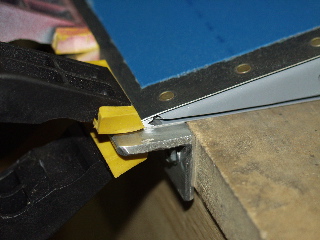
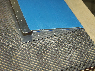
| The most interesting (and stressful) part was making the bends in the skin. I had made a bending break from some discarded lumber, and I used it here to compress the trailing edge. Next, I used the little blocks that I had cut out of the v-clamps to create a setup similar to what is pictured in the manual. By going slowly, and by using another piece of wood to "push" the aluminum into place, the bends turned out pretty good. |
|
| |
|
4/6/04 - 3 hours - Trim Tab
I had to use my rivet gun to attach the spar since I don't yet have a longeron yoke for my squeezer. This was fine until I tried to attach the control horns. One rivet in particular was drilled out several times, and I had to eventually drill out to a #30 hole and use a flush-head pop rivet instead. |
 |
| |
|
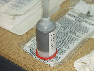
Next, I did ProSeal. I combined this step with the trailing edge on my new rudder so I only had to do ProSeal once.
I used the pre-packaged cartridge that Aircraft Spruce sells. This makes mixing the two parts a lot easier, but I probably ended up wasting about half of the container.
I put the cartridge in my regular caulking gun, and while it worked, it is apparent that the dedicated Semco gun would work a lot better. |
 |
| |
|
I wore gloves and had lots of rags handy. When I inserted the ribs they wanted to hold the skin open, which is why I had the V-clamps that I had made. However, I may have used a bit too much pro-seal because I had to "augment" the v-clamp with a c-clamp to hold it tightly together. I'll let you know in a few days if it worked.
Update: I may have used a bit too much ProSeal on the rib because I had to really squeeze the skin so there wasn't a bulge. |
 |
| |
|
4/11/04 - 1 hour - Trim Tab Hinge
With the trim tab complete and dry, I had to figure out how to get the hinge attached to the elevator. The instructions say to attach the hinge to the trim tab and then clamp it to the elevator so it can be drilled. This is fine except with the hinge attached to the trim tab, there is no apparent way to clamp the other side of the hinge to the elevator. |
 |
| |
|
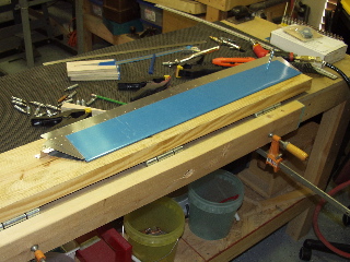
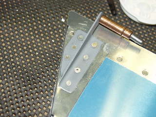
| So, I drew a line on the hinge where the rivet line should be, and then I clamped it in place with the line showing through the rivet holes in the skin (just like I did on the trailingn edge of the elevators.) Then I drilled the holes, working from the center and putting a cleco in every hole I drilled. It turned out good. |
 |
| |
|
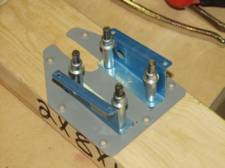
4/12/04 - 2 hours - Servo Cover
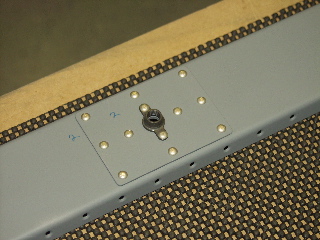
The elevator trim servo comes with two brackets which must be riveted to the little hatch cover on the left elevator. There aren't many details about how or where to attach these, so here's what I did.
I clecoed the brackets to the servo and placed the servo on the cover plate where it would clear the exit hole properly. The instructions do say that the brackets must be 3/8" from the back edge of the cover. Then, I marked around the edges of the brackets with a marker. I removed the servo so I could access the holes in the brackets and match-drilled the holes into the cover and into a piece of lumber, clecoing as I went. |
 |
| |
|
After deburring, dimpling, and priming, I riveted the brackets to the plate, and then attached the servo. The front two rivets interfere with the servo, so I squeezed (or is it squoze?) the front two rivets until they were really flat.There was still a bit of interference, but basically the servo just sits snugly against the front two rivets.
I will attach the control rods and clevises later when the elevator is attached to the plane. |
 |
| |
|
| Next: Wings! |
|
| |
|