| |
|
Everything I have read so far about building one of these planes seems to point to three or four really difficult and unpleasant tasks which must be accomplished by the builder. The fuel tanks are one of these feared tasks. Vans even sells completed fuel tanks for some of their planes, although I don't think they sell them for my plane. The cost of these prebuilt tanks is not trivial. I think they are around $700 apiece.
The problem with doing the tanks is that there are a lot of tasks which must all be accomplished at once to create a tank that doesn't leak. Where on other parts of the plane a rivet is simply squeezed or bucked, the tanks use ProSeal to seal the rivet head. This apparently makes a big mess all over your tools and clecoes, and is not a whole lot of fun. Especially if you find a leak afterward and have to repeat part of the process.
Well, the plane won't be very useful without fuel tanks, so here goes... |
| |
|
5/28/04 - Tank Ribs - 4 hours
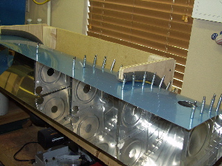
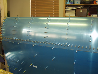
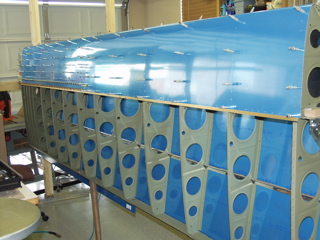
Using my leading edge cradles I worked on assembling the tank ribs into the skins. Because of the way I built the cradles I am able to turn the tank on it's side and work on it sideways. This turned out to be really nice.
I went ahead and removed the blue plastic from the inside of the tanks. I considered leaving strips of plastic inside the tank during assembly, but I decided it would be more trouble than it was worth. |
 |
| |
|
The top side of the skins attached more easily than the bottom side. To get the rib set into the skin I placed a scrap piece of 2x4 under the leading edge at the tip of the rib. This allowed me to apply pressure to the rib so I could see the hole through the skin hole.
After placing the frontmost cleco, I placed a cleco in every hole. This helped to assure that the rib was lined up properly. After it was set, I was able to remove half of the clecoes. |
 |
| |
|
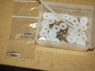
| I took a few minutes to take a look at the capacitive sensors that I received with the kit, but I hadn't opened it yet. Inside I found six pieces of aluminum, a spool of wire, two BNC connectors, and a mess of connecting hardware. It also contained an instructions sheet and a new plan sheet showing the detailed assembly of the capacitive sensors. |
 |
| |
|
| |
 |
| |
|
| Back to the tanks. The Z-brackets must be drilled so they can be attached to the tank baffle. The instructions say that I have to drill these brackets using a drill guide with a hole in the center. I am good at messing up these types of drilling operations, so I decided to wait until tomorrow to do these. |
 |
| |
|
5/29/04 - Stiffeners - 2 hours
My friend, Todd, who is nearing completion of his Sonex, stopped by this morning to look over my project and to act as an informal technical counselor. I showed him some things I had done wrong, and this helped me make some decisions as to how to proceed.
I spent the rest of my morning cutting and deburring the tank stiffeners. These are cut from long strips of angle, just like in the empennage. |
 |
| |
|
5/31/04 - Lots of work - 11 hours
Today is Memorial Day, and my wife and kids were at the in-laws, so I was able to spend the entire day working on the -9A.
I started by drilling the tank stiffeners to the skins. |
 |
| |
|
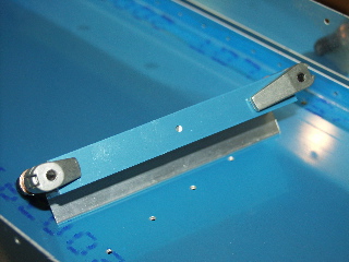
I was a bit apprehensive about drilling the attach angles, since doing it incorrectly would result in tanks not lining up on the wing.
So, I started by re-reading the instructions. After I thought I had it figured out, I started by clamping the alignment tool onto the flange. I aligned it by placing it flat on the workbench and making sure the bracket and the alignment tool were flush. Next, I drilled the alignment holes in the center of each of the flanges except for the inboard-most bracket. |
 |
| |
|
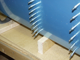
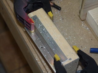
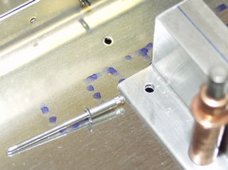
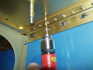
For drilling the hole, I found that it works best if the bracket is supported behind the hole so I can apply consistent pressure with the drill. I used a chunk of 2x4 as shown in the picture.
Next, I had to draw little lines centered on these new holes. It took me a few tries on some of them, because my line drawing tool is sometimes hit and miss. Fortunately I can erase a line with a little Acetone. |
 |
| |
|
| On one flange the hole needed to be enlarged to 3/16" holes. To do this, I used the same block of wood, clamping each angle to it before drilling out the hole. This might sound unnecessary, but these brackets are difficult to deal with unless they are clamped to something. |
 |
| |
|
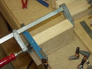
| Now comes the time where I have to line up my centering line in the holes in the baffle, and then clamp it in place. I have found that clamps are bad about not holding with pressure from drilling, so I had to go slowly and not apply a lot of pressure. Every time I finished drilling one of the holes, I would put a cleco into the hole to minimize the chance that the bracket would move. |
 |
| |
|
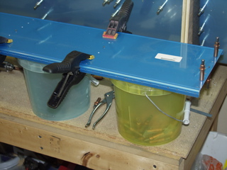
| Here's a cool tip. I bought several buckets at Lowe's that I use to hold my clecoes. These are sturdy and semi-transparent, and I like that they have a handle on them. Well, I found that these are also great for holding the baffles up while I drilled. They are exactly the right size to keep the baffle from sliding around during drilling. Nice. |
 |
| |
|
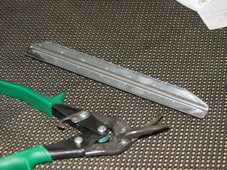
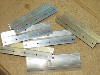
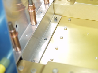
| Here are the brackets as they looked after I finished drilling and deburring them. There are five 1/8" holes on one flange, and one 3/16" hole on the other flange. |
 |
| |
|
| Lest anyone is thinking of bothering my project, here's a picture of my extremely fierce guard dog. :-) |
 |
| |
|
| In order to be able to install the tank on the wing, there can't be a bunch of clecoes holding the brackets onto the baffle. So, Van's suggests using pop-rivets to hold the brackets in place. These are drilled out later. |
 |
| |
|
| I had to modify my junky pop-riveting tool so that it could fit up close enough to the bracket. I ground down the top until it was pretty much paper thin, but it worked. I was able to pop-rivet the brackets without any trouble. |
 |
| |
|
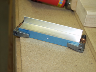
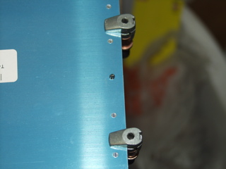
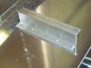
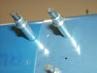
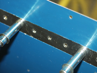
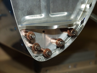
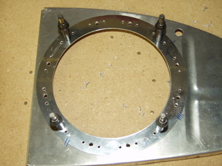
Here is one of the brackets with the pop-rivets holding it in place.
Oh, yes. The brackets do not face the same direction. I had to double and triple check the orientation. Otherwise, I could miss the holes I'm trying to attach them to. |
 |
| |
|
| Next, I got to attach the tanks to the wings. Fun. I put clecoes in every hole attaching the tank skin to the spar. |
 |
| |
|
To drill the brackets, I had to access the spar from the bottom of the wing. The bottom skins as you may recall are off the wing at this time, so I got "inside" the wing and drilled through the spar into the brackets. This was slow going because I didn't want to move the bracket during drilling. |
 |
| |
|
| The most dramatic moment was the actual drilling of the inboard-most bracket. This one doesn't have any holes in it yet so that the correct offset can be correctly drilled through the spar and into the bracket. I was relieved to see that my holes came through properly. |
 |
| |
|
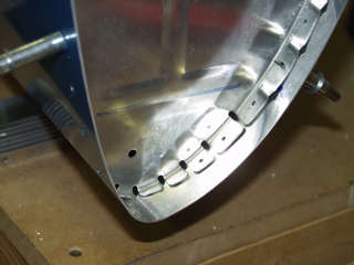
| Here is a picture of where the tank and the rest of the leading edge connects. |
 |
| |
|
| One more picture of the bottom side of the wing with the tank installed temporarily. |
 |
| |
|
| After removing the tanks once again, I commenced countersinking the holes along the tank baffle. These are countersunk instead of dimpled because it is easier to install the baffle when it is covered with ProSeal. |
 |
| |
|
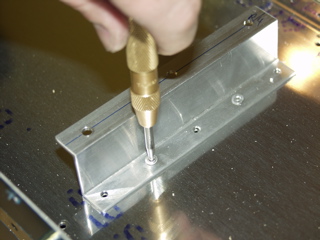
Time to remove the pop rivets, which is sort of a pain, but much less painful than having to build the tank on the spar, which is what I would have to do otherwise. I drove the shaft out of the center of the rivet using my center punch.
That about does it for me for today. |
 |
| |
|
6/1/04 - Platenuts - 2 hours
Once drilled, the Z-brackets receive platenuts on the side that attaches to the spar. I don't have a platenut drilling tool, so I used a spare AN3 bolt and one of the platenuts as my drilling guide. For each hole I bolted the platenut into proper position. Next I drilled one of the 3/32" rivet holes and put a cleco in the hole to hold the platenut from turning. Then I drilled the other rivet hole. Wash, rinse, repeat. There is no picture of this process, but you will see the results soon.
I ordered the fuselage kit today! There is a 10 week lead time on the kit, so I decided I better get the thing ordered or I would be sitting with nothing to build here in a few months. I expect it by late August, but I'll know better when they send the confirmation letter. |
| |
|
6/4/04 - Tank Attachment Brackets - 2 hours
These brackets are cut from 2" x 2 1/2" aluminum angle. This stuff is nearly 1/4" thick.
One tool I have elected not to purchase is a bandsaw, because there are so few times that I need to cut parts out of raw material, it didn't seem like a good use of my tool budget. In this case I could have saved a lot of time if I had been able to use a bandsaw. |
 |
| |
|
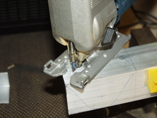
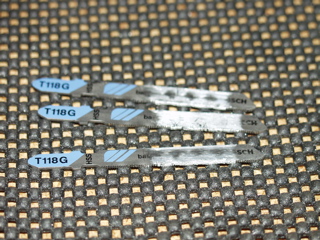
| Instead I used my jigsaw. This tool works pretty well for most things, but with this material I had to go very slowly unless I wanted the aluminum to melt and stick to the blade, which happened quite a bit. It is likely that I didn't have quite the correct blade for the job, but I didn't want to go to Home Depot for just one thing, so I had to work slowly. |
 |
| |
|
 |
 |
| |
|
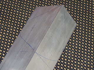
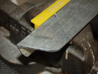
I transferred the full-size pattern from the plans to the material by first tracing the pattern onto copier paper, then cutting the pattern with scissors, and then finally tracing around the outside of the paper pattern with a marker. There are also some hole positions specified on the plans which I transferred to the material by holding the pen on the paper and letting the ink bleed through to the metal underneath. Although this made a light mark, it was enough to be able to see where the hole was supposed to go, and I could then mark it's location directly on the metal.
I cut on the outside of the marked line, and then I used the scotchbrite wheel to shape it closely to the line. |
 |
| |
|
6/5/04 - Brackets and Fuel Senders - 5 hours
The brackets I fabricated attach to the fuel tank at the tip of the inboard rib. The holes that I had drilled in the brackets needed to be match-drilled to the rib. The only reference point for making sure the bracket is in the correct position is the edge of a dented stiffener. Since this edge is difficult to see, I enhanced it by tracing along the edge with a marker. |
 |
| |
|
| The result looks like this. |
 |
| |
|
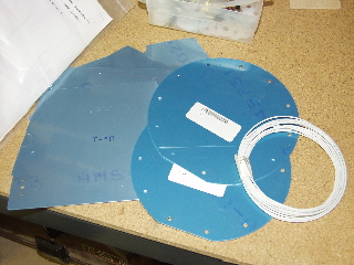
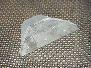
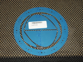
There is also a doubler plate which is roughly the same shape. This doubler goes on the inside of the inboard rib to provide more structure to the attachment bracket.
These plates come pre-formed in an odd formation like you see here. The outer ring is for the access hole which I'll work on later.
The doubler plate needs to be cut to final shape, and then slight adjustments are made to make sure that the edges fit nicely to the inside of the tank skin. |
 |
| |
|
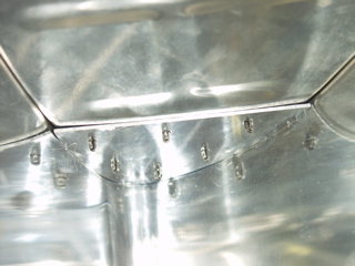
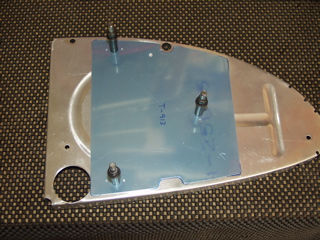
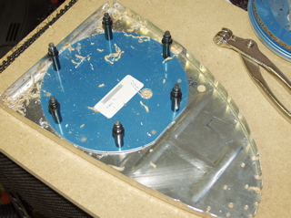
| This is what it looks like on the inside of the tank after I attached the doubler plate using clecoes. |
 |
| |
|
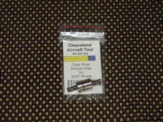
| My order from Cleaveland Aircraft Tool came today. It is a set of Tank Dimple Dies. These are supposed to dimple a little more deeply than the standard ones, so that when I set the rivets coated in ProSeal they won't protrude out from the skins. I understand that some people partially coutersink the dimples after the dimple is formed using their deburring tool. That probably works too, but I am hoping that this way is a bit quicker and more accurate. |
 |
| |
|
Next, I moved on to the capacitive fuel senders. These are just a set of aluminum plates mounted to the inside ribs of the fuel tank. The kit has separate instructions from the main instructions, as well as a separate plan sheet. I spent some time studying these before drilling the ribs.
The ribs are match-drilled, using the holes in the plates as guides. These holes are then enlarged to 1/4" only on the ribs, leaving the holes in the plates as #20. |
 |
| |
|
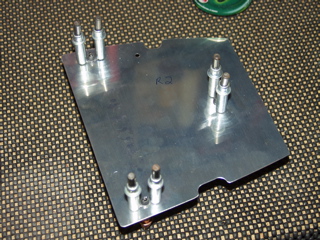
| Here is one of the plates with the platenuts drilled and ready to be countersunk and riveted. |
 |
| |
|
6/6/04 - Misc. - 2 hours
I didn't take any pictures today, but I got some random things accomplished. I countersunk the rivet holes for the fuel sender plates and then riveted on the platenuts. Next, I modified the snap bushings so they could accept the wire in addition to the vent tube. I also soldered the wire onto the BNC bulkhead fittings. Finally I cut one of the access holes from the interior rib using the fly cutter in my drill press. |
| |
|
6/7/04 - Inboard Tank Ribs - 3.5 hours
To start off, here is a picture of the snap bushings that I made a notch in to accept the wire. You can't really see the notch too good, but it is on the inside of the top.
Today I had to fix my drill press because the fly cutter caused the mandrel to separate from the tapered shaft. I whacked it a few times with a hammer and it appears to be working properly. I have found this to be a good solution for nearly all problems in life, except those related to parenting.... |
 |
| |
|
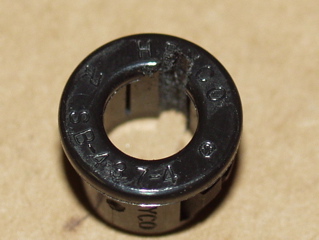
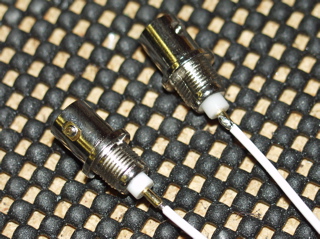
| These are the BNC connectors which fit into the tank to allow the capacitive fuel senders to be disconnected easily if the wings or tanks should ever need to be removed. These must be soldered to a length of wire, which I did yesterday but didn't have a picture yet. Well, here's the picture. Isn't it exciting? |
 |
| |
|
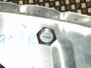
| I marked where the connector needed to be mounted by establishing the rough edge distance specified in the plans and then placing the nut for the connector onto the rib to estimate the center point of the hole I needed to drill. I used a spring-loaded punch to put a dimple in the center. Next, I drilled a #40 pilot hole in the center. Finally, I enlarged the hole with a Unibit. |
 |
| |
|
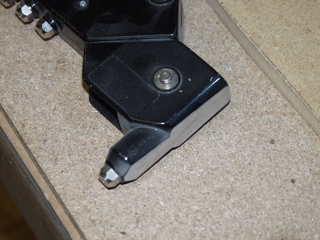
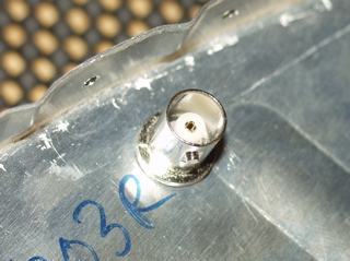
| Here is one of the BNC connectors as it will eventually be installed. |
 |
| |
|
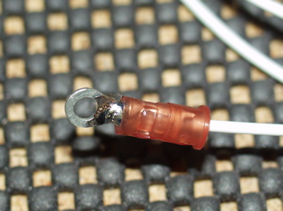
| Another task is to attach a ring terminal to another length of wire. First I crimped the ring terminal onto the wire using my new ratcheting crimpers, then I flowed solder into the end of the wire, forming a small fillet between the end of the wire and the ring terminal. Fortunately I didn't damage the jacket. |
 |
| |
|
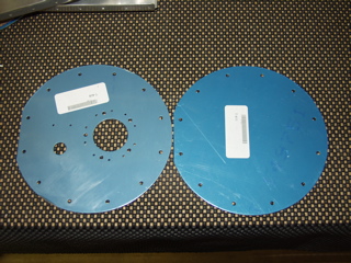
| The capacitive fuel senders come with alternate cover plates for the fuel tanks. These plates do not have the holes for the float-type fuel senders. The only problem is that I still needed the fuel pickup holes, which are not drilled either. To remedy this, I clecoed the T-408 to the T-411 and match-drilled the holes. The larger hole had to be enlarged with the Unibit. |
 |
| |
|
| Here it is after I finished. |
 |
| |
|
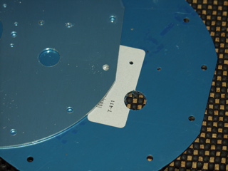
Next, the T-411 is used to match-drill the end rib, making holes for the screws which will eventualy hold the plate in place.
The strange part about th is process is that there is no way to make sure you are centered around the hole in the rib, so when I finished I had about a 1/16" offset from being centered on the hole. It's not a big deal, but it just looks odd. Maybe I'll do it better on my next plane! |
 |
| |
|
Here is the T-407 after I drilled the platenut rivet holes to the rib. The platenuts are installed prior to sealing the tanks.
At this point the rib is dimpled, and the T-407 is machine countersunk to accept the flush rivets that hold the platenuts in place. Care must be taken to properly orient the T-407, the platenuts, and the rivets to make sure they all go on the inside of the tank. The T-411 plate goes on the outside of the tank. |
 |
| |
|
| Next: More Fuel Tank Stuff |
|
| |
|