| |
|
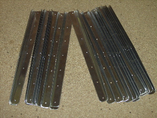
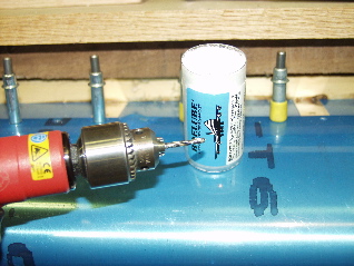
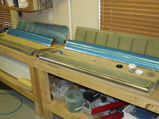
8/8/04 - Aileron Prep, Stiffeners - 7 hours
Hey, this is kind of like building the empennage! The skins are paper-thin, there are a million stiffeners, and I get to back-rivet! This should be a breeze! ...except for those pesky trailing edges...and ProSeal...and what are these enormous water pipes for?
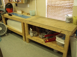
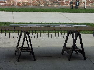
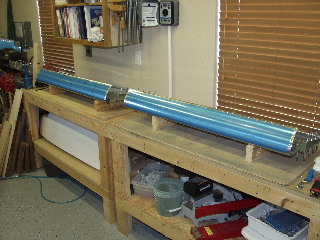
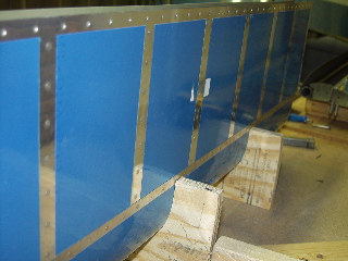
I set up my work tables end-to-end so I will have a nice, long space upon which to build the ailerons and flaps. The ailerons are short enough to be done on one bench, but the flaps are quite a bit longer. |
 |
| |
|
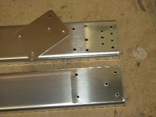
I started with the doublers. I have decided that the best way to build these, like the wings, is to build them at the same time, and make a mirrored copy. That way I won't inadvertently build two left ailerons. That would be bad.
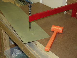
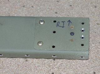
So here are the doubler plates. They only have five of the holes drilled. The rest must be back-drilled through the spar. The easiest way I found to orient myself to the direction of the spars was to look for the platenut holes. These go on the inboard side of the aileron. |
 |
| |
|
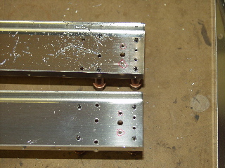
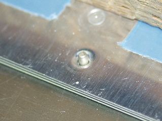
| Here they are, back-drilled. Yes, this is probably an unnecessary picture. Although most of these holes are #30, be careful because some of the holes are #40. These will be dimpled to accept flush rivets, so the bracket can be mounted with bolts. |
 |
| |
|
| Next I had to match-drill the end ribs to the spar. You have to take care not to put the wrong one on the wrong end. They sort of don't fit very well if you don't use them in the right place. If you find yourself having to force them in, you've got them backwards. |
 |
| |
|
| Here are the outboard ends, just to show that they are indeed mirrored. |
 |
| |
|
| The nose ribs are funky looking. Here they are, match-drilled to the spar. |
 |
| |
|
The instructions are sort of difficult to understand here, so it took me a little while, and a peek at the Orndorff video, to determine exactly what to do.
The idea is to align the two nose ribs so that they are in their proper, permanent position so that the counterweight pipe can be properly drilled. The plans say to put the skin on the outside of the assembly and cleco the ribs. I found that this wasn't exactly what was needed. In fact, after some fiddling, I found that the best solution is to use the opposite skin for this purpose. (right aileron skin on left aileron assembly) This made the holes line up properly to make the ribs nice and straight. |
 |
| |
|
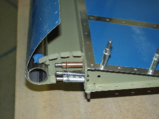
| So now you can see what this is all about. This is just a temporary setup that allows me to mark the locations of the two holes that need to be drilled in each end of the counterweight pipe. Once you mark the pipe you can take the skin back off. |
 |
| |
|
| Here is the pipe after it has been drilled and clecoed to the nose ribs. |
 |
| |
|
The instructions call for pop rivets to temporarily attach the pipe to the ribs. These are to be drilled out later. The only thing is that I really dislike drilling out pop-rivets, so I decided to try something else instead.
I noticed that you can easily use a cleco for one of the holes without any interference. I tested it with the skin in place. For the other hole, I used a suggestion from the video. I put a regular solid rivet in the hole and taped it in place. While this doesn't provide any shear strength, it should serve to properly align the rib during the next several steps. |
 |
| |
|
| Just to see if it would all fit together that way, I temporarily clecoed the skin on. Yep, it should work. |
 |
| |
|
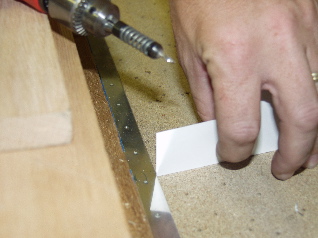
| Next come the stiffeners. There are a mess of stiffeners to cut, trim, shape, and debur. It goes just like the ones in the empennage, so I won't elaborate here. |
 |
| |
|
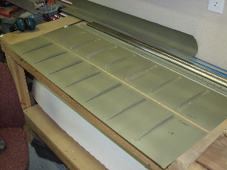
| Here are the top and bottom skins of one of the ailerons. It is important here to verify the orientation of the skins prior to drilling the stiffeners. They go together like a sandwich, and the stiffeners overlap. The plans indicate that you use all the right stiffeners on the right aileron and the left stiffeners on the left aileron (or is it the other way around, I don't remember.) |
 |
| |
|
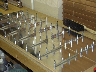
8/11/04 - Scuffing Parts - 4 hours
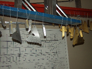
In preparation for priming, I scuffed all of the parts for the ailerons, as well as the parts I still need to attach to the rear spar (aileron and flap hinge brackets.)
Now that the fuselage parts are here I really want to get the wing finished up so I can move on. |
 |
| |
|
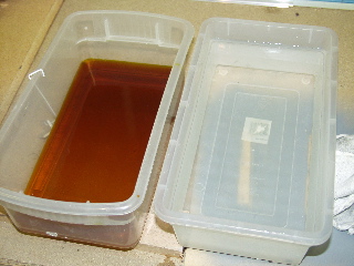
8/12/04 - Alodine - 1 hour
Before I drag out the spray equipment to do another batch of priming, I decided to alodine the aileron and spar hinge brackets. I figured these could use a little extra protection.
I have found that Alodine really works best if you can submerge the part, so I have elected not to alodine any parts that are only receiving primer on one side, like top skins. |
 |
| |
|
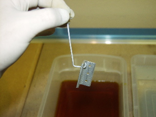
Here is a quick rundown of how I alodined the hinge bracket parts. Before starting, I used Alumaprep to etch the parts. I did this last night, and I hung them up to drip-dry.
First, I put the Alodine in one rubbermaid bucket, and some clean water in another.
I use small metal hooks (that I fabricated out of my wife's clothes hangers) to hold the parts during the process. These parts have not been touched since I etched them with Alumaprep. Notice I am using latex gloves to protect my hands. |
 |
| |
|
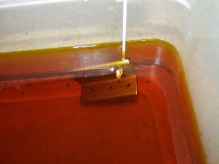
Here goes. I dip the part into the Alodine, and keep it submerged for about a minute. I count to 60 in my head (since I don't have that many fingers) and that seems to work fine. The longer the part is submerged, the darker it becomes.
Try to keep the part from sitting on the bottom of the tank. I have pulled parts out on occasion which had been sitting on the bottom, and you can see where the Alodine didn't permeate the aluminum. What you want is Alodine on all sides. It sometimes helps to move the part around in the tank to make sure you are getting good coverage. |
 |
| |
|
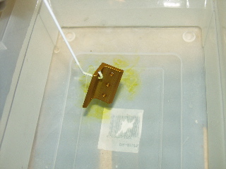
When the time is up, remove the part from the Alodine and immediately submerge it in the clean water. Swish it around a bit to clean it, but don't touch it.
No, I'm not a chemist. The instructions are on the bottle. :-) |
 |
| |
|
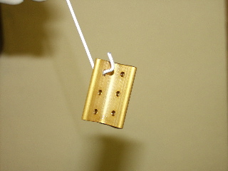
When you are finished the part will be a nice golden brown like you see here. The part can be hung up again to dry.
I have written about this before, but it is worth repeating. Don't put Alodine in the sun. The sun will zap it and you will end up with a bucket of brown liquid. |
 |
| |
|
Here are my parts. In this picture I am about halfway through, so you can see some are gold and some are still bare.
The Alodine causes some sort of a chemical conversion on the surface of the aluminum which is resistant to corrosion. Superior uses this process on their engines instead of paint because it is lightweight and doesn't restrict the dissipation of heat.
These parts could be left just like this, but I am going to spray a coat of primer on these parts for extra protection. |
 |
| |
|
8/13/04 - Priming, Assembly - 7 hours
I spent most of the day deburring and scuffing, followed up by a few hours of priming. I got all the parts for the brackets and ailerons primed. I will do the flap parts when I need them. |
 |
| |
|
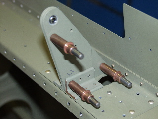
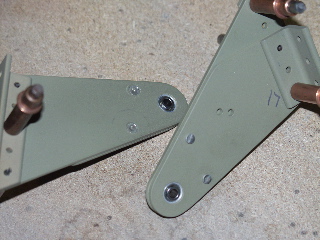
After priming (and cleaning the spray gun) I reassembled the brackets, making sure I got the right pieces together, which I had marked before I took them apart.
There are some flush rivets which must be installed on the correct side of each of these brackets, as well as a couple which are very difficult to install after all of the parts are together, so I recommend looking at the plans carefully before driving any rivets. |
 |
| |
|
 |
 |
| |
|
 |
 |
| |
|
| Well, at least now I have lots of things to rivet together. |
 |
| |
|
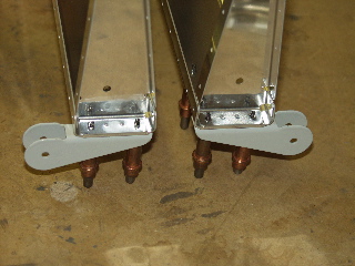
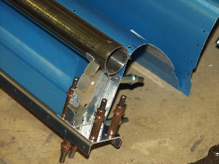
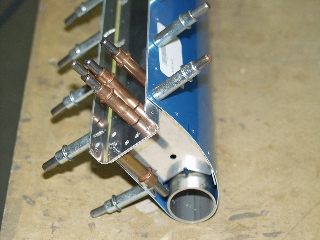
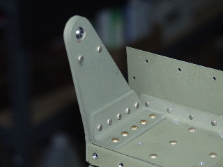
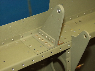
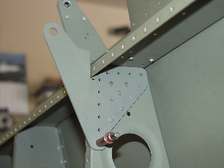
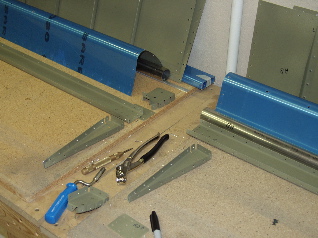
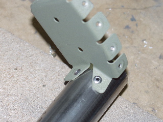
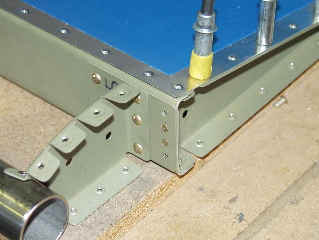
8/14/04 - Aileron & Flap Brackets - 5 hours
My dad came up from Houston today so I had to show off all of my progress. He reads the site regularly but hadn't seen it in person since Christmas. Obviously I've done a lot since then.
I did get the aileron and flap hinge brackets mounted. It takes a while because there are lots of rivets and limited access. |
 |
| |
|
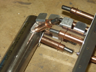
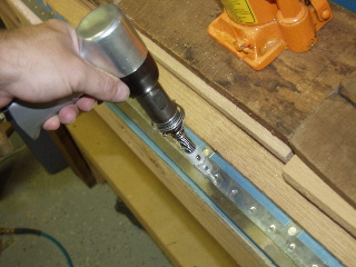
| The offset rivet set is a royal pain to use. I've gotten so that I can shoot near perfect rivets by myself using the straight set, but the offset one is always an adventure. I probably drilled out a dozen rivets because of the silly thing mashing up the rivet heads. |
 |
| |
|
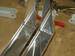
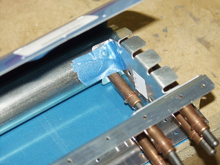
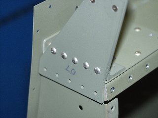
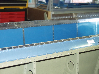
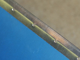
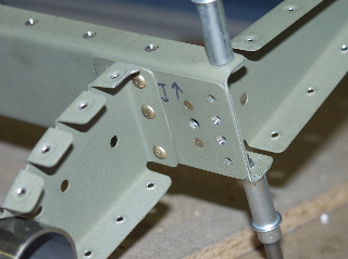
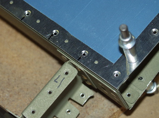
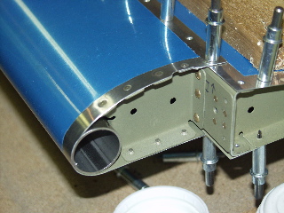
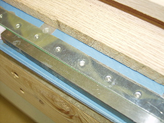
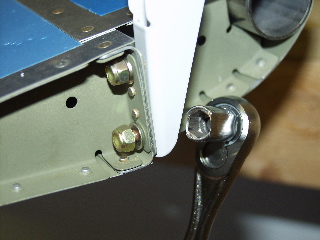
| Here is an interesting picture. It shows the flush head rivets on the back side of the spar on the inboard side. There is a flap control that comes through near here, so there can't be any rivets poking up. |
 |
| |
|
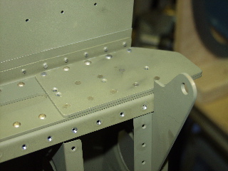
8/15/04 - Aileron and Flap Gap fairings - 5 hours
Although this took a while because of the large number of rivets, it was rather rewarding work.
The riveting process had scuffed up the trailing edge a bit, so before I installed the gap fairings, I used some 988 primer from a spray can to spray some primer on the places where I could see bare aluminum. Since this stuff dries quickly, I was ready to continue in just a few minutes. |
 |
| |
|
| This is a terrible picture, but I wanted to show that there are flush head rivets that connect the inboard side of the gap fairing. |
 |
| |
|
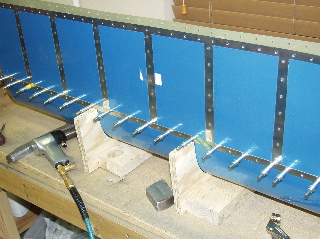
| Here they are, all nice and riveted. |
 |
| |
|
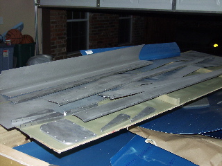
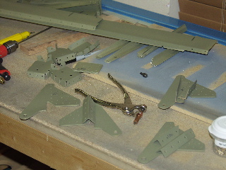
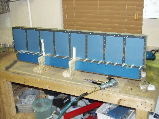
Here's an interesting thing for my Ailerons page: actual Aileron parts!!! I sort of got sidetracked putting the finishing touches on the hinge brackets and gap fairings, but with those out of the way I am now ready to rock and roll on the ailerons.
I dimpled all of the skins and stiffeners. Next step: back riveting! |
 |
| |
|
8/16/04 - Assembly - 4 hours
I got all of the stiffeners riveted to the skins. This is fun riveting and it went quickly. I had labeled each stiffener so I knew where it needed to go.
When I finished riveting, I started attempting to assemble the ailerons. Immediately I could tell something wasn't quite right. The holes on one of the bottom skins did not line up with the holes on the spar. I switched spars, thinking it might have been labeled incorrectly, but no. I had goofed again. Apparently I had prepped the wrong side of one of the bottom skins. |
 |
| |
|
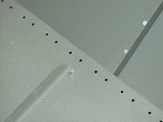
Originally my thought was to just order another skin and redo it, but then I started looking at the skin itself and realized that the only problem was that the top row of rivet holes were not matching up to the spar, and would therefore not match up to the nose skin either. All I had to do was to match-drill a new set of holes along the top of the skin, and leave the old holes alone. So, I used the other skin to match-drill a new set of holes, and this is what it looks like.
I have plenty of edge distance between the old and new holes, so I don't think there will be a problem. I will call Vans to make sure. |
 |
| |
|
Update: I spoke with Bruce at Vans and after explaining the situation to him he agreed that this was fine and that he would do the same thing that I did. I now have some additional lightening holes in my plane! :-)
Assuming that it will be fine, I went ahead and assembled the ailerons according to the plans. It says to install temporary rivets to attach the bottom skin to the ribs. This is so it can lay flat on the worktable. |
 |
| |
|
| As soon as I installed the nose skin I realized why they tell you to put weights on top of the skin to keep it flat. The trailing edge looks terrible. The nose skin is thick and stiff, so it pulls the skins apart, with more force applied in the center of the spar than on the sides because the sides are reinforced by the ribs. The result is that the trailing edge of the skins show signs of stress. |
 |
| |
|
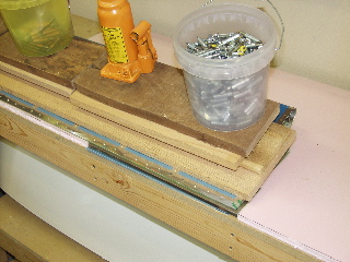
So I found some boards and stacked them on top of the aileron to keep it flat. Tomorrow I will try to find some bags of lead shot or sand or something heavy.
So today's lesson is to always double-check any part that is somewhat symmetrical to make sure I don't inadvertently use it backwards. This boo boo wasn't that big a deal, but it still bugs me that I did it wrong. Fortunately it was an easy fix and nobody (except for you) will ever know of my mistake. ;-) |
 |
| |
|
8/17/04 - Match Drill, Debur - 4 hours
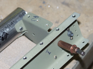
I started with the holes in the leading edge stainless steel tubes. I had read where these are difficult to drill, so I first made some punch holes in the centers of each hole with my spring-loaded punch. This is a handy tool that is about five bucks at Harbor Freight. I use it for lots of drilling tasks that require a little "starter" dent for the drill bit to sit in. I also use it to remove rivets after I drill off the head. It is much more convenient than trying to swing a hammer inside of the wing structure. |
 |
| |
|
I also used a new, sharp drill bit for each aileron, and I used Boelube on the drill bit before each hole.
With the combination of the spring loaded punch and a sharp drill bit, these holes weren't that bad. I turned the drill really slowly and tried to get those nice, spiral shaped shavings coming out. That's when you know the bit is cutting the metal and not just chipping it. I think the sharper the drill bit, the better, because I could tell when the bit was getting dull. |
 |
| |
|
| After drilling the remaining holes in the skins, it was time to drill the trailing edge. Once again the plans call for an angle perpendicular to the chord of the control surface, so I made a card with the side cut to the correct angle. Then I could place it up against the drill and visually match the angle of the drill to the angle of the side of the card. Worked like a charm. |
 |
| |
|
After drilling, everything was disassembled once again. I am always amazed how many metal shavings are inside when I disassemble after drilling. It indicates how important it is to follow the instructions on deburring. The last thing I want is a bunch of little sharp pieces of metal lodged in between the skins.
With the Olympics on the TV, I spent a while deburring the holes. This is sort of mindless labor that takes a lot of time, but doesn't requier a high level of concentration, so I watched swimming and gymnastics. I wonder when they'll add RV flying to the Olympics... |
 |
| |
|
Finally, after reading several other builder's comments, I decided to go ahead and edge-roll the top edge of the nose skin. The way it bends around the top of the aileron can lead to gaps between the rivets, which I wanted to avoid. Although I've had bad experiences with the edge-rolling tool, I decided that this thick material would not disfigure, so carefully I gave it a shot. It helps to do this before you dimple, because dimples get in the way of the rollers, so I rolled the edge prior to any dimpling. The results look good so far. We will soon see if this makes a difference in the final assembly.
Ladies and Gentlemen: Now competing in his first Olympic event, Edge Rolling! |
 |
| |
|
8/18/04 - Final Assembly - 4 hours
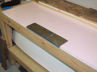
I started by dimpling and countersinking. Countersinking the angle is a bit strange, but I used the technique I came up with on the empennage where I use a small piece of scrap angle underneath the workpiece to hold it perpendicular to the countersink.
Once that tedium was finished, I started assembling and riveting the parts. I'm just going to show the pictures of the assembly process. It's easier than typing! |
 |
| |
|
 |
 |
| |
|
 |
 |
| |
|
 |
 |
| |
|
 |
 |
| |
|
 |
 |
| |
|
 |
 |
| |
|
I had to stop because it was almost 10pm and I don't want the local neighborhood association to outlaw airplane building!
The only real issue I had was that the clecoes along the spar didn't want to hold securely to the countersunk holes. They may have been slightly enlarged, but more likely it's because there just isn't much metal left at the bottom of the countersink.
As a result of this I decided to use slightly longer rivets along the spar so that I get a better shop head behind the spar. This has turned out to be a good decision because the 3.5 rivets were just a little too short. |
 |
| |
|
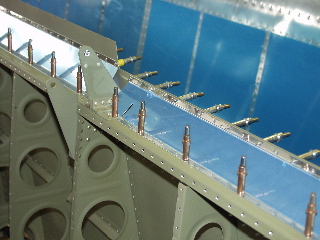
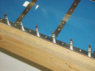
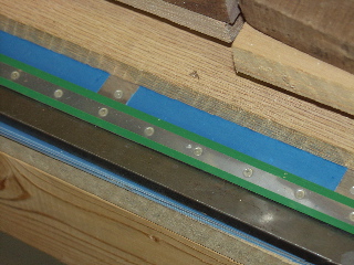
8/19/04 - Riveting - 3 hours
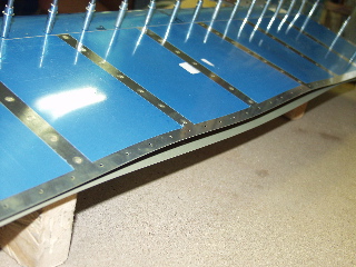
I got the second aileron riveted to match the first. The main issue that I discovered was that the trailing edge was extremely wavy. I am pretty nervous about riveting the trailing edge because even with the trailing edge clecoed it is still wavy. Look at the picture below to see what I am talking about. The reason is because the nose skin is stiff and causes the spar to "open up" and cause the skins to have stress. |
| |
|
 |
| |
|
8/20/04 - Riveting - 4 hours
The instructions at this point do not say to use ProSeal to seal the trailing edge like it requires for the empennage. I assume it wouldn't hurt to do the ProSeal, but I got to thinking about it and decided that the reason the ProSeal is used on the rudder and elevators is because those control surfaces are not flat, so there has to be something holding the trailing edge together during riveting. The ProSeal does not provide any structural adhesion over the life of the airframe, it is only for the assembly process. So, seeing how much I dislike ProSeal, I decided to simply follow the directions and not use ProSeal. |
 |
| |
|
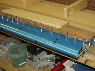
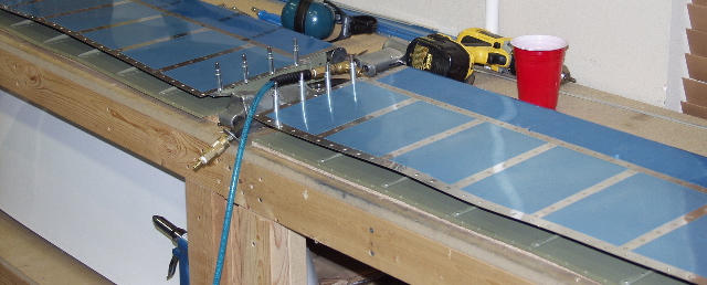
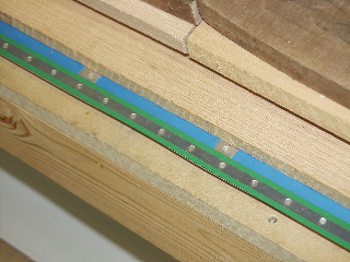
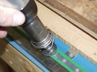
I wanted to keep the surface weighted and flat the whole time I was riveting, so I went to Home Depot and bought some 1/2" insulating foam board. I cut a piece the size of my workbench and cut out a spot for the back-riveting plate.
Next, I clecoed the trailing edge together, skipping every other hole. This lines up the holes. I put long pieces of oak and walnut boards on top of the aileron to hold it flat against the table and keep it from opening up. Then I put rivets in each open hole, and I removed the other clecoes and put rivets in the remaining holes. |
 |
| |
|
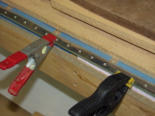
The rivets called for on the plans didn't seem long enough, so I went to the next longer size just for safety. This worked out well.
Next, I put riveting tape on the line of rivets.
I couldn't move the aileron at this point without some temporary clamps because otherwise the skins would spring open as soon as I removed the weights. So, I used small spring clamps to temporarily hold the trailing edge together while I flipped it over. Then I placed even more weight on top of the wood. |
 |
| |
|
 |
 |
| |
|
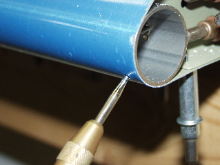
Here is what each of the rivets look like prior to back-riveting. It is at a slight angle, so you can't just back rivet it straight down. You have to sort of sneak up on it by back riveting straight and then making slight adjustments until the gun is perpendicular to the skin.
Don't try to drive the rivet all the way into the dimple. |
 |
| |
|
 |
 |
| |
|
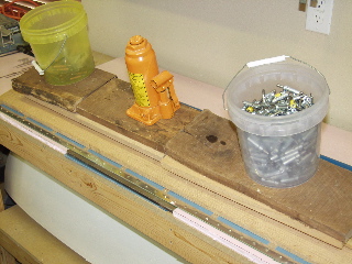
I riveted the center rivet about halfway, then I drove every fourth rivet about halfway.
I had to move the aileron back and forth across the back riveting plate, since it isn't long enough.
Eventually I finished back-riveting, so I could flip the aileron over and use the mushroom set to finish driving the rivets. |
 |
| |
|
 |
 |
| |
|
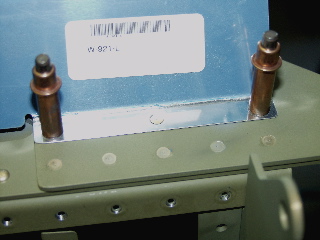
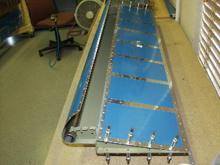
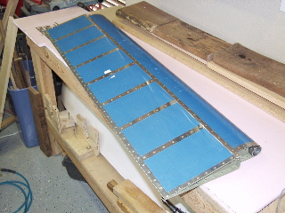
Here you go. One completed trailing edge. Amazingly it is straight and true. I definitely am happy with the way they turned out.
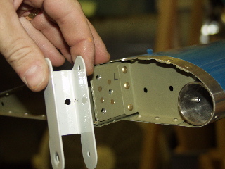
Next I installed the hinge brackets. I had to modify a 3/8" socket so it could fit inside the brackets. You can see it in the picture below. |
 |
| |
|
 |
 |
| |
|
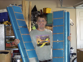
| Two completed ailerons, one tired builder. Notice the shirt. |
 |
| |
|
| Next: Flaps |
|
| |
|