| |
|
Previous: Cabin Plumbing |
|
| |
|
1/7/05 - Customization - 8 hours
Up to this point I have tried to stay very close to the instructions set out by Van's. I have not done any real customization, except for the baggage floor thing. I have heard tales of how modifications can add weeks or months to the project, and I really don't want to do that. But...
Have you ever looked at the instrument panels in those composite planes and said "wow, that looks great"? Me too. In fact, the more I thought about it, the more I wanted to implement something different from the stock panel in my plane. |
 |
| |
|
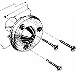
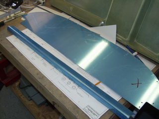
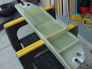
But first let me show you what the stock one looks like and basically how it gets installed.
The panel itself sits on the forward decks and is screwed to the 7017 and 7108 panel supports. You build up a set of flange pieces that are riveted to the upper skins, and platenuts are attached to these flanges so the panel can be screwed (and unscrewed) from the substructure.
So this is how it looks the way Vans has you build it. |
 |
| |
|
 |
 |
| |
|
At this point, if you do not care to see the steps I took to customize the panel, you can skip the rest of this page.
I wanted to do three things: First, I wanted to improve the looks of the panel. I wanted something a bit more shapely than the flat piece of aluminum that Van's sells. Second, I wanted to create "attention zones" in the panel, where I could visually divide the instrumentation into a more intuitive human interface. Finally, I wanted a modular panel which could be easily updated and maintained later on. |
| |
|
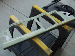
At first I planned on making my own composite panel, but I have yet to do any composite work, so that plan was doomed to failure. fortunately I found a panel that I could purchase that works for my purposes.
I saw this panel in a plane at SWRFI last year, and I was determined that this was the one for me. It has removable aluminum insets on which the instruments are mounted. After quite a bit of research, I found that this panel is sold as a kit by a builder named Laird Owens (owens@aerovironment.com). After a bunch of emails back and forth, I finally sent him a check, and just the other day the box arrived with this. Ain't it cool?! |
 |
| |
|
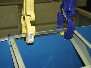
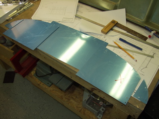
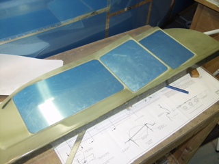
The instructions that Laird includes with the panel instructs you to use your existing panel as the source for the necessary aluminum that will be needed to mount the new panel. So the first step is to cut the bottom flange off the panel. This piece will be used as angle when mounting the new panel.
Next I needed to cut up the remaining panel to fabricate the insets. One snag was that the instructions for the panel were made for the old style Vans kits, where the panel is apparently not cut to size and not pre-punched, so I had to carefully plan my cuts in order to obtain the three insets from the material available. |
 |
| |
|
 |
 |
| |
|
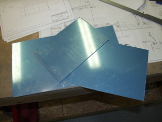
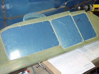
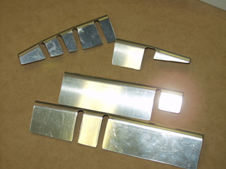
Next, I had to round the corners to match the shape of the indentions in the composite panel. I did this using both a sanding disc and the Scotchbrite wheel.
This was mostly a trial-and-error process, with the results being three nicely fitting panel pieces.
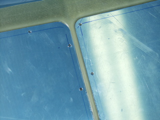
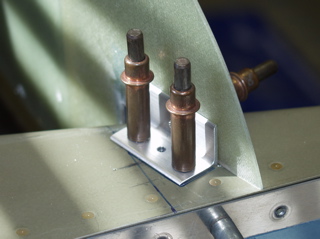
Next I measured to locate the screw holes, using the plans supplied with the panel. The instructions called for the insets to be screwed into place (with temporary hardware) to add some strength to the otherwise lightweight panel. |
 |
| |
|
 |
 |
| |
|
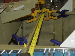
| The next step is to carefully measure the airframe where the panel will be installed. The panel is made larger than necessary, and it is up to me to cut it to fit, starting with the lower portion of the panel where it will connect to the sides of the fuselage. |
 |
| |
|
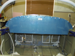
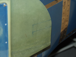
This step involved a lot of measuring and marking, along with the placement of a temporary piece of angle to establish the correct location for the panel.
After checking and re-checking the measurements, I took a deep breath and started cutting, using a die grinder and a dremel tool, both with abrasive cutoff wheels, to carefully cut just inside the lines I had marked. |
 |
| |
|
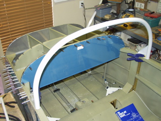
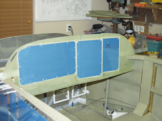
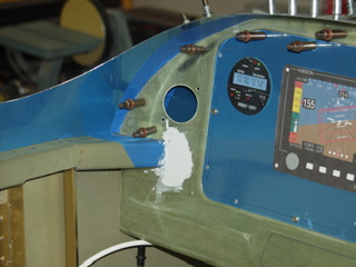
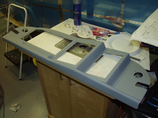
Now for the tricky part. I had to get the panel to fit around both sides of the forward canopy decks. This meant I had to remove all of the forward structure that I had previously clecoed into place. Only after doing this was I able to (just barely) snap the panel around the decks and into place. Unfortunately it's going to have to come out a few times, but at least I know it's going to fit!
Doesn't it look great? I'm very pleased with this so far. Just wait until I add the instruments, radios, efis, etc. It's going to be great. |
 |
| |
|
1/8/05 - Supports - 6 hours
Today I made the required modifications to the existing panel supports by cutting off the old end flanges and fabricating new ones. These are going to eventually be epoxied to the back of the panel. |
 |
| |
|
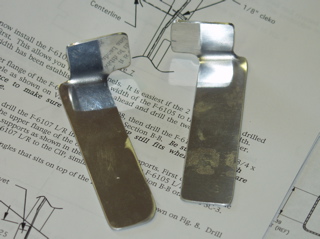
This picture shows it better. The original part had a flange on the end, but didn't come out far enough to attach to the new panel, so this piece takes its place.
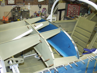
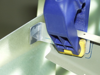
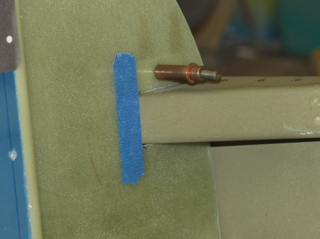
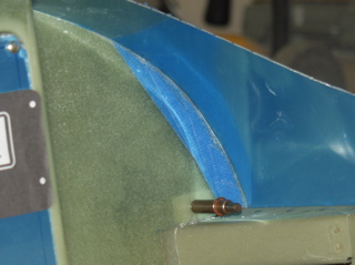
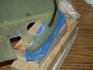
Next I worked on the sides. These are attached in much the same way as the stock panel, except the angle is more pronounced. These angle pieces are pop-riveted to the deck.
The piece of blue tape is where I need to do some fiberglass to fill in a space that I cut too deep. |
 |
| |
|
 |
 |
| |
|
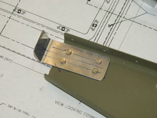
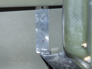
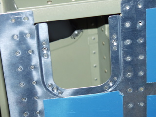
To account for the difference between the non-prepunched and prepunched planes, I had to deviate a bit from the instructions and fabricate these support pieces. I made them so they would make use of the holes that are already drilled in the side of the fuselage. They bend 90 degrees and a platenut will eventually go on the bottom.
Finally I spent a while trimming the panel to fit just right underneath the top skin. I've got more work to do on this as it is a slow process of trial and error. |
 |
| |
|
 |
 |
| |
|
1/10/05 - Nothing - 0 Hours
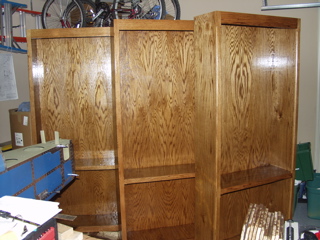
As soon as I started trimming the panel I realized that it was impossible to contain the dust that I was generating. As I am also trying to finish three bookshelves for my wife on the other side of the garage, I decided I'd better finish the bookshelves first and get them out of here before I make any more fiberglass dust.
So, I spent the evening putting urethane finish on my bookshelves. |
 |
| |
|
1/11/05 - Trimming the Panel - 1 hour
I spent an hour fitting and re-fitting the upper skin, using a file to make small adjustments to the fiberglass panel. I have to say it is better, but not perfect. I probably need to add some epoxy in a couple of places. |
| |
|
1/13/05 - Learning about Fiberglass
The bookshelves are out of the garage. Hooray. They were a birthday present for my wife, so I'm glad I took the time to make them, but boy I really needed the garage space back!
I spent some time emailing and reading about the correct way to add on to the fiberglass panel. Laird sent me some great pictures to describe the process. I've never done any fiberglass, so this is all new stuff to me. I also went shopping to buy some Evercoat and some urethane primer. Hopefully this weekend I will get this stuff all figured out. |
| |
|
1/14/05 - Fiberglass, Misc. - 4 hours
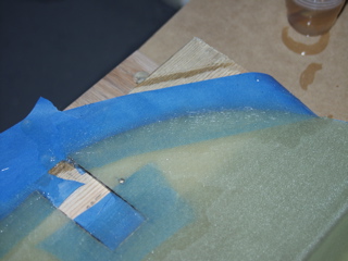
After much consideration, I went ahead and removed the panel from the plane and added a fiberglass "patch" to the spots where I needed more material. I used masking tape behind the panel to form the "mold", and then I added three layers of cloth, overlapping the edge of the panel by about 1/2 inch. Being that this was my first attempt at doing fiberglass, I didn't quite know what to expect. It seemed to take longer to start to harden than I expected it to. Then I remembered reading somewhere that epoxy resin is temperature sensitive, and it needs to be warm. So I moved the layup into the house where I left it to cure overnight. |
 |
| |
|
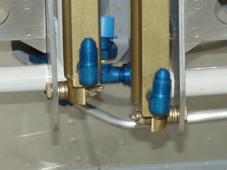
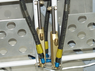
Since I couldn't do any more work on the panel, I went back to the brakes and worked on those for a while. I located the correct fittings and, using EZ-Turn, screwed them into the master cylinders. I also went around to each of the pressure fittings I have installed in the cabin and I torqued them to the correct values.
Next I installed the high-pressure hoses to the brakes, discovering soon after that I needed them removed so I could install the brass fittings for the low pressure side. |
 |
| |
|
| I installed the brass fittings and then reinstalled the hoses. I had intended to go ahead and install the low pressure lines to the brake reservoir, but I discovered that Vans had sent me the incorrect tubing. The tubing I received was .032 thickness, and the plans call for .063. So I placed a call and they are supposed to be sending it right away. |
 |
| |
|
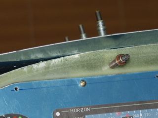
The last thing I did was to test fit the engine mount on the firewall. The instructions tell you to trim the platenut and screw holding the fuel pump, so I first tightened the screw into place, and then I used the die grinder to cut about 1/8" off the platenut and screw. Now the engine mount will fit.
I went searching for the mounting bolts for the engine mount and discovered these were on backorder from Vans, so I had to quit for the day. |
 |
| |
|
1/15/05 - More Fiberglass, Vents - 6 hours
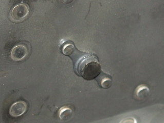
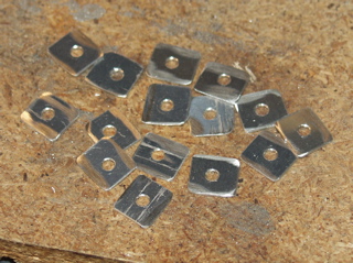
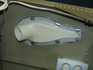
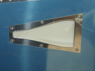
The fiberglass is still curing, so I decided to do the NACA vents. I swear I looked through the entire instructions and I couldn't find any reference to installing them, but I read enouugh from other builders to figure out what to do. I know that some builders just attach these with Proseal and be done with it. I decided to use a few rivets. In order to fasten it securely, I made some more of these little square washers to go on the back side of the vent. So here's a picture collage of the process. |
 |
| |
|
 |
 |
| |
|
 |
 |
| |
|
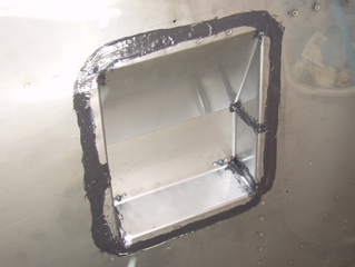
| While I had the ProSeal mixed, I went ahead and sealed the firewall recess. In hindsight I probably should have installed this with the ProSeal between the firewall and the recess, but I really hate "wet" riveting, so I put it off until now. |
 |
| |
|
| In the afternoon I went back to the panel and trimmed the new fiberglass. It worked, although my rookie fiberglass is full of little air holes, so I'll need to fill it. |
 |
| |
|
| Finally, I spent a while fabricating the mounting angles for the fiberglass panel. These are made from the leftovers from the old instrument panel. |
 |
| |
|
1/16/05 - Attach Angles - 3 hours
It took quite a while to make the attach angles fit properly. There is some geometry on the composite panel that must be taken into account, and I was trying to make use of as many of the prepunched holes as possible. So, naturally this process took way longer than I expected it to.
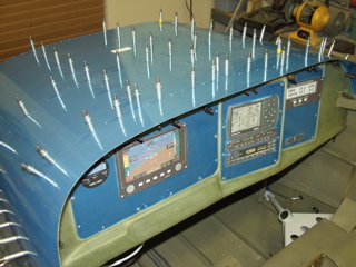
After getting everything attached to the panel, I clecoed the top skin back on. First I match-drilled the prepunched holes where they could be used. Next, while laying on my back underneath the panel, I match-drilled the new holes through the attach angles and into the skin.
For those who are wondering, I will go ahead and drive rivets into the remaining prepunched holes. Even though they will serve no purpose, they will fill the holes and make it look more finished. |
 |
| |
|
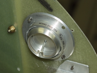
1/17/05 - Air vents - 2 hours
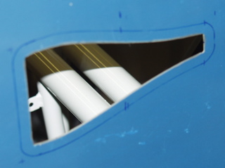
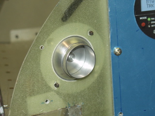
I didn't like the plastic vents that came with the kit. They looked like something from a McDonald's Happy Meal. So I bought a pair of aluminum eyeball vents that Matthew Brandes recommended. These are so much nicer that they don't even compare. Anyways, I decided I should figure out the mounting of these before I went any further with the finishing of the panel.
The vents have a flange which is intended to go in front of the panel, but I sort of like the cleaner look that you get with the eyeball protruding through the panel itself. The only catch is that the hole needs to be perfect. |
 |
| |
|
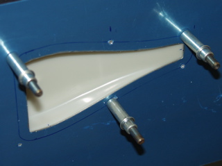
The other catch is that I have to figure out how I'm going to attach these. I can probably use countersunk screws into the fiberglass, but I'm thinking that it might be possible to epoxy these directly to the panel, which would be an even cleaner installation, I think.
Oh yes, I have ordered some 2" aluminum vent flanges from Vans since there isn't much to attach to on the back of these vents.
I'm pretty happy with these vents so far. |
 |
| |
|
1/18/05 - Fiberglass - 2 hours
After fitting all of the angle support brackets I still had a small gap on the left side of the panel, so I finished drilling a couple of holes and then made a "tape template" of the space that needeed filling in. I did this by cutting some masking tape so that it just covered the opening. Then I removed the entire panel and added a larger piece of masking tape as a backing "mold."
I did the layup indoors because the garage is still really chilly. Tomorrow I'll trim it. |
 |
| |
|
| I've also been spending some time figuring out my engine situation. I have an o-320 that needs to be overhauled, and I'm thinking about doing it myself. Go to my new engine page for more information. Today I made a reservation to attend the Mattituck engine workshop in March. Basically I'll get to watch an engine being built, along with a group of other folks, and we'll ask questions along the way. I figure it'll be good to see the process in person and up-close. |
| |
|
1/19/05 - More Fiberglass - 5 hours
The layup from yesterday is cured, so I trimmed and filed the edge to the edge of my taped line. Then I reinstalled the panel and prepared to bond the attach angles to the fiberglass. This was done using T88 structural epoxy. The skin is used sort of as a clamp to make sure the angles are in the correct position. Before I did this I had to install a few platenuts. I also had to countersink the holes that match holes in the skin which will eventually be dimpled.
With the glue drying, I used some Evercoat to fill in a couple of low areas where my layups didn't quite match the surface of the panel. This stuff dries quickly. |
 |
| |
|
| Looking around for something to do, I decided to install the access panels at the rear of the fuselage. These panels use #6 countersunk screws and nutplates, so there was the usual nutplate installation process to go through. |
 |
| |
|
1/20/05 - Primer, flood lights - 5 hours
The epoxy has cured so I removed the panel from the plane. It's a bit tricky to install and remove the panel, since it is such a close fit to the sides of the cabin. What I have to do is get it as far forward as possible, then put one of the side cutouts around the forward canopy deck, then slightly bow the panel to get the other cutout up and around the other canopy deck, and finally slide it back into position. It's sort of nerve racking to be bending it like that, but it has worked so far. Hopefully soon I can install it permanently. |
 |
| |
|
| Next I cut out the openings in the panel, leaving 1/2" for the subpanels to connect to. The 1/2" lip will receive platenuts, but I'm not sure of the correct process for installing platenuts in fiberglass. I'm sure there's a way to do it, but right now it's confusing me for some reason. I suppose I need to countersink the fiberglass to accept the flush rivet heads. |
 |
| |
|
| After I made the cuts I sanded and then put on an initial primer coat. This showed all of the "pinholes" that are apparently a common part of working with fiberglass. So I mixed up some more Evercoat and attempted to fill some of these pinholes. I also filled the temporary cleco holes that I had drilled during the early part of the assembly process. |
 |
| |
|
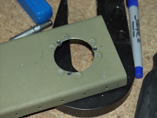
| While waiting for the primer to dry on the panel, I began fiddling with these miniature flood lights that I purchased a while back. I have been planning to install them somehow on the side covers of the 904 bulkhead, but up to now I haven't really figured out how I would go about doing it. I didn't want the large "hockey puck" part of the light to be exposed, but the side covers are going to be pop-riveted into place, which means I won't have any service access to the lights if I installed them from the rear. |
|
| |
|
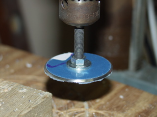
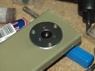
So I came up with an idea of using an aluminum faceplate, and mounting the eyeball behind it. At first I was just sort of messing around with the idea, but the more I worked on it, the more I liked it. The process was to take a 2.25" (or so) aluminum cutout made from .063 alclad and chuck it in my drill press, which I used like a lathe to smooth the edges of the disc. Then I enlarged the center hole to 7/16" or so, just large enough for the eyeball to move freely.
Next, I used the mounting holes in the light assembly as a template to drill the holes in the faceplate. |
 |
| |
|
 |
 |
| |
|
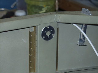
I used #6 countersunk screws and K1100-06 nutplates to attach the faceplate to the side covers. This required a 1.5" hole to be cut into the side cover, and then carefully I drilled holes in sort of an opposite pattern from the first set of mounting holes. I then installed the nutplates. I will most likely rivet the light assembly to the faceplate once the faceplate has been painted.
One cool thing about this setup: When I finally get around to putting in the fabric or vinyl interior, these faceplates will go over top of the fabric, giving it a very finished look. |
 |
| |
|
| Next: Firewall Stuff |
|
| |
|