| |
|
Previous: Avionics 1 |
|
| |
|
6/10/05 - 6/15/05 - Wiring - 15 hours
Over the past week I have been getting all the wires connected to the various pieces of equipment in my instrument panel. If you are paying someone to make a custom wiring harness for you, then you would save the time that I am spending, but I enjoy this part of the project.
I have also been neglecting the website a bit because there's really nothing too interesting to report. I will take a bunch of pictures when I'm finished wiring. |
| |
|
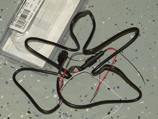
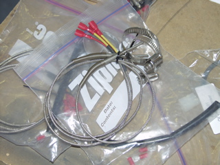
One thing I had to figure out was how I was going to attach the output of the Garmin 196 GPS to the rest of my system. I didn't want to hard-wire the connector to the equipment, as I may wish to change to a newer GPS at some point in the future. So, the first thing I did was to order this bare wire connector that Garmin sells for the 196. It has four wires: power, ground, data in, and data out. It is wired with an inline fuse, which I will not be using. |
 |
| |
|
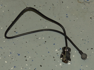
Here is the cable after I wired a DB9 connector on the other end. This is a bit longer than I needed, but it'll do.
My plan is to mount a DB9 connector on the subpanel that abstracts the GPS connection from the rest of the system. This will let me change to a new type of GPS at a future date by just exchanging the adapter cable. |
 |
| |
|
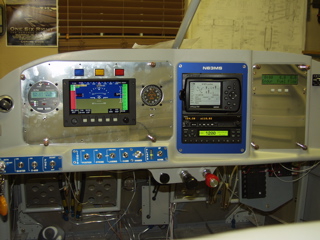
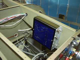
| I added two switches to the main panel. These are small micro-switches that I bought from Radio Shack. The first one is a DPDT switch that turns on and off the EFIS and AHRS. This allows me to leave these devices off during engine start in order to extend their life. The process will be to leave this switch in the off position while starting the engine. The EIS4000 is always on, so I will use it to watch RPM and check the oil pressure. Once the engine is running, I will use this little switch to turn on the EFIS. |
 |
| |
|
The switch is wired to switch the EFIS power and the AHRS power. These are each on a different fused circuit.
The other switch I installed is to selecte the data source for the autopilot. I can now select either the EFIS or the GPS to control the autopilot. I will probably use the EFIS most of the time, since I can select to follow either a heading or a flight plan, but if I ever have a complicated flight plan that I have programmed into my GPS, or if the EFIS becomes inoperable for whatever reason, the switch will change the input to the GPS data feed.
Regardless of the position of this switch, the EFIS will continue to receive GPS data. |
 |
| |
|
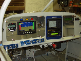
| Another wiring challenge has been attaching the SL40 and GTX327 to the EFIS. There are software settings on each of these devices which control how they operate when attached to another device, so I have been playing with these while sitting in the cockpit making airplane noises through the intercom on my headset. I'm sure by now my family is ready to send me to the nuthouse. Anyways, this is sort of a fun puzzle, where everything needs to match up in order to work. |
 |
| |
|
| The wiring has also been challenging because I hope to be able to pull out the subpanels for maintenance or whatever. This means that I can't have anything hard-wired to the panel, including the switches. So, for the switches and indicator lights I am using a DB9 connector so that these features can be unplugged when the subpanel comes out. Who knows, I may want to upgrade at some point, and being able to easily remove the subpanels will be a definite advantage. |
 |
| |
|
6/17/05 - 6/18/05 - Misc. - 8 hours
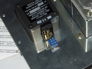
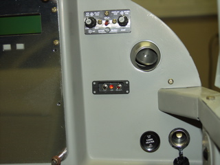
Tying up some loose ends on the panel, I installed the ELT control head. This thing serves little purpose other than to be able to see if the ELT transmitter has accidentally been activated. I put it way over on the right side so the passenger can monitor its status. :-) I guess this thing also will let you reset the transmitter. The little head apparently has a battery in it that I will need to replace every couple of years. |
 |
| |
|
| At this point I need to wire the stuff forward of the firewall to the engine monitor. I havea certain amount of apprehension about this. Not because it will be difficult, but because it means attaching stuff to the engine. I guess I am a little intimidated by the engine, and it's something I need to get over, so here goes. |
| |
|
| I dug up the probes that came with the EIS4000. These are the EGT probes. I don't have the exhaust installed yet, so I can only look at this at the moment. |
 |
| |
|
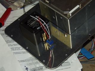
I installed the oil pressure sensor. This thing will tell the EIS what the oil pressure is in the crankcase. It's pretty simple to install, since there's only one lead to attach.
Next I figured out the cylinder head temperature probes. These attach with a little bayonet fitting that is screwed into the bottom of each cylinder. I verified with GRT that these are just hand tightened, as there is no way to get a tool on them anyways. Todd said the spring will hold them in place. |
 |
| |
|
 |
 |
| |
|
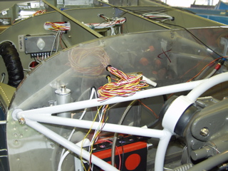
| These probes need to attach to the EIS, so I spent a while routing the wires through the firewall. For good measure I'm trying to keep these wires away from any power or ignition wires. I'm hoping that I will be able to attach them to the engine mount. The probe wires are pretty long, so I'm not sure where the best place will be to make the connections. There will also be a big box around the engine (the baffles), and the wires will need to be fitted through these plates I think. |
 |
| |
|
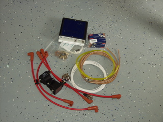
Here are the parts supplied with the Lightspeed ignition. I noticed after I took this picture that I didn't put the hall effect sensor in the picture.
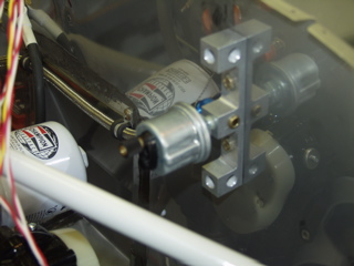
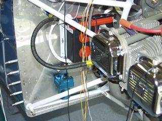
I found a nice place to install the ignition controller. I installed platenuts on the rib so that I can remove this thing if necessary. I emailed Dan C. a while back and he said he has had no reason to access this box, and that it works great in this position, so this is where I'm putting it. Next, I mounted the ignition coils on the top of the engine. I removed one of the case bolts to install the coils. I think I need a little bit longer case bolt to replace it with. |
 |
| |
|
 |
 |
| |
|
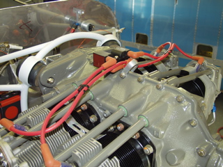
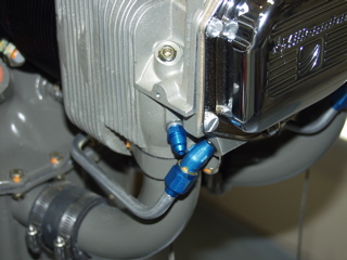
The ignition coils can be separated if necessary, which is good because I was unable to fit the assembly in place and get the bolt through the holes until I disassembled them. I then attached the little bracket to the engine and then reassembled the coils.
Here's where the ignition wires exit through the firewall. Don't worry, these little exit points will all get gooped up with ProSeal in due time.
The electronic ignition requires a feed from the manifold pressure sensor. What? I didn't think I needed a manifold pressure sensor. |
 |
| |
|
| Well, after some searching, it seems Van's has included the manifold pressure kit as part of my finishing kit, so at least I have the connection, but I didn't order the sensor from GRT, so I guess I'll be giving them a call on Monday. I also realized that I don't have a fuel pressure sensor. Sensors are good, as they provide information to the displays, so I don't have a problem ordering them. It's just that I had never thought this far ahead, and now I'm definitely charting new territory. |
 |
| |
|
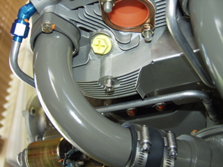
| Here's something a bit odd: the manifold pressure hose is about a mile long. It's huge! I think it would rub the cowl if I leave it as-is. So, I'm wondering if people are shortening the hose, or just putting an s-bend in it to keep it away from the cowl? |
 |
| |
|
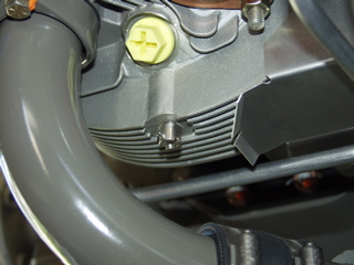
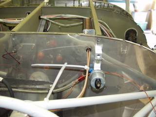
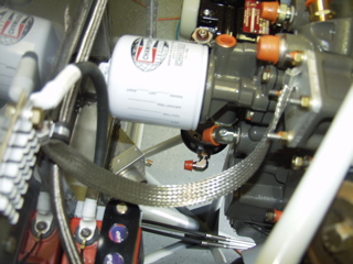
Here's my ground strap. Currently it's attached to one of the bolts on the now-empty vacuum pump boss. I had B&C make this strap for me, but I think it's a bit too long if I use this location.
So you can see that I am still technically connecting stuff to the engine monitor, but I really am looking at the forward part of the firewall at this point, so I should probably make a new section on the website.
Next: Canopy
Also: Firewall Forward 1 |
 |
| |
|