| |
|
Previous: Empennage & Landing Gear |
|
| |
|
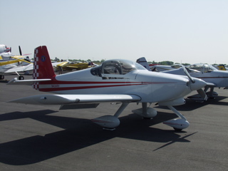
5/21/05 - Texas RV Fly-In
I had decided that if I could get the engine installed, I'd go down to the Texas RV Fly-In at the Midlothian/Waxahatchie airport. I'm glad I did. It was a beautiful, but hot, day in Texas, and there were more RVs there than I have seen since Oshkosh. I got to meet several builders/pilots who I had only previously only communicated with via email, which was really cool. I also met some new builders, which is also great. The more the merrier. You can see my pictures of the event by clicking here. |
 |
| |
|
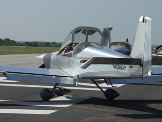
Of course, the absolutely coolest thing was that I finally met Clay Romeiser, who has often offered to take me for a flight in his -9A, but I have each time been busy or unavailable. I think Clay was busy all day with demo rides, but nobody appreciated it more than I did, except maybe Matthew, whom I also met for the first time. It was cool to have BBQ lunch with a bunch of RV-9A builders/flyers. You don't get to do that every day.
Clay's RV-9A is a lot like mine will be. The major difference is that his has a tip-up, and mine has a slider canopy. |
 |
| |
|
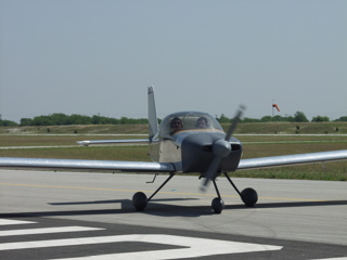
His panel is also totally computerized as mine will be, but his has the big screen Blue Mountain EFIS, which was very nice. Mine will have a smaller single screen GRT EFIS, which is not as fancy, but does most of the same things.
His engine is a 160hp o-320 by AeroSport with a single lightspeed ignition, which is identical to mine. He has a Sensenich fixed pitch metal prop, where mine will be a Catto three blader. So, this really is a close representation of how mine will fly. One thing I noticed immediately was how smooth and quiet his engine was at idle. We could still carry on a conversation inside the cockpit with th engine idling. I asked him about it later because Vans' factory -7A demonstrator was much more noisy. Clay said he has lots of foam insulation at the firewall and on the floor. I also think the o-320 is probably quieter than the angle valve o-360.
Now, about my flight with Clay: we took off to the south into very little wind, and he was complaining about the 90° weather and the poor performance. I was marveling at how fast we were climbing. There was an inversion layer up past 3000 feet, so it was rather warm where we were flying (about 2500 feet MSL). The air vents provided adequate cooling. Once we reached altitude, he handed me the controls and I was doing some very gentle turns. He took the controls back and demonstrated some aggressive turns of probably 60° or more, which was awesome in the tip-up canopy. I have to say that if I hadn't already committed to the slider, I'd have serious second thoughts about the tip-up.
We're really moving along now at more than 140 knots. This thing really accelerates. Clay slowed it down to 70 knots and it was still very responsive. We then did a power off stall, which was much more gentle than the stall in the -7A I did last week. The -9A kept flying and flying until a brief shudder and the nose fell straight down. Recovery really involved only centering the stick. We didn't even add power. I think we lost all of about 50 feet. Amazing.
We turned back towards the airport and I followed the highway as we talked. Clay managed power, and we descended to pattern altitude without much trouble at all I was setting up for entry into the pattern, expecting him to take the controls at any time, but he didn't. Instead he handled radio and power, and let me fly the pattern. We cut power abeam the runway, and he had me raise the nose to bleed off airspeed. He said we wanted 70 knots for approach. I think he dialed in some flaps at that point, but I'm not sure. I was still thinking he'd take the controls for landing, but he said to begin a shallow turn to base, so I did.
Wow, what a great way to fly a pattern. There is no wing or ceiling (or anything at all) blocking your view of the runway! My shallow turn was a little too shallow, and I had to correct for final approach, but we were in great shape altitude wise, so it wasn't an issue. Now comes the interesting part. I'm used to Cessnas, which basically fall to the ground when you cut the power. The -9A was definitely different. I held the nose up, but I guess not enough, because we floated, and floated, and floated. Finally we touched down gently (I think) and Clay had me hold the nosewheel off the ground for another 100 feet or so. He then took the controls for the taxi. It was probably the worst landing at the fly-in, but it was my first, both in an RV and to a fly-in, so it was special. |
| |
|
So I am completely sold on the -9A. I think if I were a student pilot I would definitely be spoiled by a ride like this. It was everything I had dreamed of when I decided to take up flying, but had not found in my years flying around in a Spam Can.
Thanks a bunch to Clay for the amazing flight, and for letting me fly so much, including the landing. I know he was handling power, flaps, radio, etc. but it was great to be able to feel the plane in all aspects of flight.
I gotta go build! |
 |
| |
|
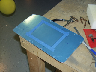
5/22/05 - Panel - 3 hours
I finally got the GRT EFIS I was waiting for. This is the center of my panel, so I had been waiting to cut the main panel section until I had this device in hand. The EFIS will connect to the engine monitor, GPS, NAV, transponder, intercom, and autopilot, so I haven't been able to wire anything until I received it. But now I have every major component for my panel, so it's time to get things finished up and working.
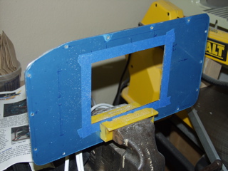
I started by making careful measurements to determine the center of the main panel. |
 |
| |
|
I have a really nice scroll saw, which does a nice job of cutting these holes, so that's what I used. I can usually keep it going in a straight line, but there are always slight variations in long cuts that I straighten up using a file. After a couple of test fits and some time with the file and the vise, the big opening appears to be good.
This is only my "prototype" panel. the real one will be cut from anodized aluminum so it matches my switch plates, but I want to make sure I have my locations correct before I commit to the CNC'd version. |
 |
| |
|
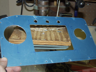
Next, I measured for the locations of the autopilot and vertical card compass, as well as the warning lights. To cut these large holes I used a fly cutter chucked in my drill press.
The position looks a little odd here, but I centered the holes vertically according to the position of the EFIS screen, not the case. I think this will have a better effect when everything is together and working. We'll see. As I said, this is a prototype. I can always cut another blank and try something different. |
 |
| |
|
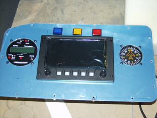
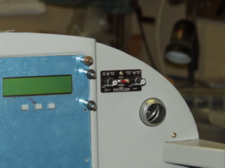
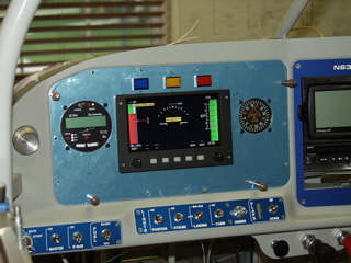
| I don't have a template for instrument screws, so it took an unnecessarily long time for me to measure, mark, and drill, the screw holes. Well, here is the first test-fit. The warning lights are: blue-voltage, yellow-EFIS warning, red-engine warning. I wanted these along the top, since I plan to look outside when I fly, and these lights are supposed to get my attention if something is wrong. The EFIS warning may be redundant because the EFIS will display the warning right in front of me. Maybe after flying a while I will take it out. Again, experience will tell if it is necessary. |
 |
| |
|
I also cut the opening for the GRT engine monitor. You can see it on the right side of the panel. I wanted it to look more integrated into the panel.
So, here's the majority of my panel all set to be wired. Pretty simple at first glance, but there's a lot of advanced mojo going on here. Now I've got to wire it up. The trick to the wiring is making each panel removable for upgrades, maintenance, etc. |
 |
| |
|
5/24/05 - Panel Work - 2 hours
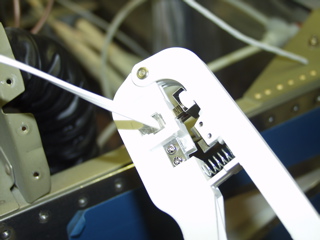
The ELT has a wire that is long enough for a 747. I didn't want all that extra wire laying around in the plane, so I had cut it a while back, leaving the cut end bare. To attach the new RJ11 connector, I went to Home Depot and bought this cheap crimping tool. It was about seven bucks and it came with some jacks. All I did was compare the end I had cut from the wire earlier to the wire as I crimped a new connector onto it, just to make sure that all the wires were in the same order. |
 |
| |
|
| I also mounted the intercom on the far right side of the panel. The -9A panel is not so large that I can't reach across the panel if I need to, and I want this device out of the way during normal operation, so this seems to be the best place for it. It also gives the passenger the ability to control music volume. I need to find some black #6 screws. |
 |
| |
|
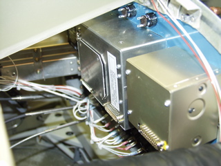
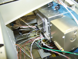
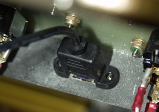
| Here's what the back of the main panel looks like. The box on the right is the autopilot control head. The big box in the center is the EFIS. The connections are all made with DB25 conectors. I will leave a service loop long enough to allow the panels to be removed without unplugging the connectors. There are two other components of the EFIS that are going to be installed. One is the AHRS, which will be placed between the forward bulkhead and the firewall on a little platform that I need to fabricate. The other is the magnetometer, which will be installed in the left wing tip. |
 |
| |
|
5/25/05 - Headset Jacks - 3 hours
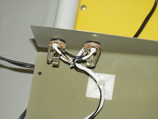
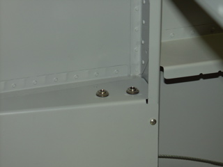
I have installed the headphone jacks behind the seats in the removable baggage side covers. This will (hopefully) allow the headphone cables to be out of the way during flight operations.
Don't ask why this took so long. Okay, I'll tell you. I started by figuring out how the little insulating washers worked, and experimenting until I knew what size hole to drill, etc. |
 |
| |
|
Then I got to thinking that it might be good to be able to remove these panels for maintenance and whatever, so I wasted way over an hour trying to attach a Mate-N-Lok connector, only to find that the connector was so large that it might interfere with the rudder cable, so I cut everything apart and just hard-wired the jacks.
I also spent a while "recycling" the D-Sub pins in the intercom connector. They are smaller than the regular ones I have, and I don't have any extras. Fortunately they were soldered rather than crimped, so I slowly and carefully desoldered each pin and cleaned the wire end so I can reuse them. This took a long time as well since there were 21 pins in all. |
 |
| |
|
5/26/05 - Right Headset Jacks, PTT Switches - 2 hours
I didn't take a single picture last night. I repeated yesterday's wiring (without the troubles) and got the jacks wired on the passenger side. I also wired the PTT switch on the pilot side and left a service loop on the passenger side for future installation.
I also placed an order with B&C for an alternator, some 22awg black wire, and some ring terminals. |
| |
|
5/28/05 - Wiring - 5 hours
Time to get the panel wired up. This is a rather daunting task that can be accomplished many ways, including paying someone big bucks to wire it for you. Of all the components of the plane that I have worked on, this is one area where I have a little experiencce, so I really wanted to do it myself.
I decided to take an incremental approach, verifying each component as I go, rather than wiring everything and then trying to figure out where the problems are. |
 |
| |
|
I decided to start with the intercom. It is interfaced with the SL40, and has room for an entertainment input, so I figured this would be a good place to start. The connector was a high density type, and as you may have read, I spent quite a while rescuing the pins from it for re-use.
Here's how my incremental wiring process works: I start with a device (like the intercom) and first hook up the power to verify that it at least lights up. After shutting off the power, I attach any external devices, one at a time, and verify their functionality. If I need to attach it to another device, I first verify the other device works by attaching it's power and ground, and then wire the interface. |
| |
|
Here's the intercom before I started organizing the wires. The wire organization is another area that can bite you if you're not careful. I had to verify that wires will not be chafing, but I also had to make sure I could still reach the rivet holes that have yet to be bucked in this forward area.
You should plan a service loop for anything that you might want to remove or maintain. Since my instrument panel sections can be removed, I want to be able to pull out the panel far enough to unplug the devices. |
 |
| |
|
| The COM radio works great, but right away I was glad I was approaching things cautiously. When I wired up the PTT switch, I tested it and quickly found that the radio was in transmit. Turn off power and track it down. I had inadvertently flipped the PTT and mic audio pins on the connector. Easy fix, but something that may have been difficult to find later on. |
 |
| |
|
5/29/05 - More Wiring - 4 hours
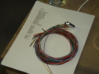
Time to dig out the wiring harnesses from GRT. These are built to a certain length, and have the connections for the AHRS and magnetometer already connected, but the remaining leads are up to me. So, I started by labeling each wire. They are all color-coded, but the labels will make it easier to sort out inside the plane.
This can be overwhelming at first. There are dozens of wires. But, continuing with the incremental approach, the first thing I did was to hook up only the power to verify the devices. |
 |
| |
|
I then spent a lot of time looking over the pinout diagrams to figure out what needs to be attached. The AHRS really only connects to the EFIS and the magnetometer. The interesting part comes in deciding what to connect to the EFIS. I only have the single screen version, which simplifies it somewhat, I think.
The EFIS attaches to just about every other device in the panel. GPS, Transponder, COM, Intercom, EIS, Autopilot, and warning light. So I have the pinouts for each device at my disposal during this process. |
 |
| |
|
It's really sort of like putting together a puzzle.
After verifying the connection between the AHRS and the EFIS, I ran the serial connection to the SL40. There is a configuration screen on the EFIS which shows if there is communications happening on each serial port, and after configuring the serial port for an SL30/40, I could see communication, although I still can't set frequencies, but we'll get that set up later. |
 |
| |
|
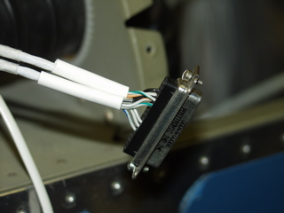
| Here is a useless shot of the back of the SL40, I guess just to show the wiring as it progresses. This should be the last of the connections to the SL40. If this were an SL30 there would be another connector with many more wires. |
 |
| |
|
5/30/05 - More wiring - 8 hours
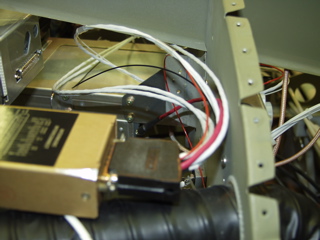
The AHRS needs to be mounted securely, and oriented in the direction of flight. After some consideration, I decided to make two rails that span the space between the subpanel and the firewall. I can adjust the pitch and roll axes if necessary by using washers or shims. |
 |
| |
|
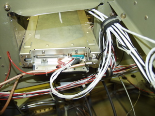
| The AHRS has one DB25 connector on the back, as well as ports for static and pitot ports. The wires that exit the AHRS go to the EFIS and to the magnetometer, which I am placing in the left wingtip. This means that the wires need to go down the firewall, along the center space, through the spar tunnel, and out the wing root. I have these wires bundled up in seat floor until the wings are attached. |
 |
| |
|
| Time to turn my attention to the EIS. The interface between the EIS and the EFIS consists only of a single serial connection, but all the rest of these wires need to be accounted for, as they will eventually connect to various sensors and probes on the engine. |
 |
| |
|
So, to keep down the confusion, I spent another hour or so labeling each wire in the bundle.
Not pictured here, but I did get the EIS powered up and communications are established with the EFIS. Immediately I noticed that my battery voltage is at 11.3 volts, which probably means I need to get a charger. I also realized that I don't have a current sensor. It's sixty more bucks. |
 |
| |
|
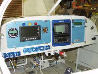
| I don't have the magnetometer attached, so there is no attitude information, but you can start to see the interface with the power applied. |
 |
| |
|
5/31/05 - Misc. - 1 hour
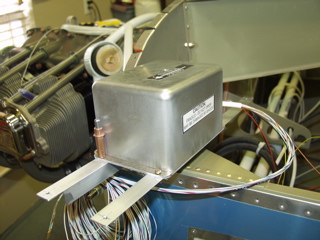
I didn't have much time but I did manage to do one or two things for the plane. I stopped by a hardware store and picked up four black #6 cap screws for the EFIS. These look better than the shiny stainless ones I had in there before. I also stopped at Radio Shack and picked up two micro switches. These don't look to be the best of quality, but I need them now, so they'll have to do. I bought a DPDT to use as an on/off switch for the EFIS and AHRS (they're on separate circuits). The other is to switch the data for the autopilot from the EFIS to the GPS if necessary. |
 |
| |
|
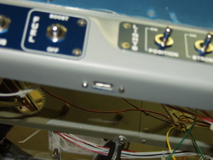
| The out of focus picture above, and the confusing picture on the right are of a little USB extension I bought from GRT last week. This pigtail plugs into the back of the EFIS and provides a convenient way of updating the software. The EFIS includes a USB thumb drive which is used to perform software upgrades and database updates. I didn't want to have to reach up inside the panel for these updates, and I didn't want to have an ugly USB connector staring at me all the time during flight, so I mounted it to the flange of the instrument panel. Nice, clean, convenient, and invisible. |
 |
| |
|
6/1/05 - Misc. - 1 hour
For those of you who will be installing a Garmin 196 or 296 in your panel, and who intend to wire it for both power and data, learn from my mistake. I grabbed the data cable that comes with the unit and cut it open, expecting to make the requisite connections. As soon as I stripped away the jacket, I realized that there are only three conductors inside. There is no power conductor in the data cable. So, I spliced the cable back together and grabbed the mobile power cable. This time I disassembled the cigarrette lighter connector and counted the conductors. Yep, three again. It seems like Garmin doesn't want you to use these cables to connect both power and data. So now I am waiting for a power/data cable that I had to special order. Garmin sells them for about $30 I think, but you can get them on eBay for a bit less. |
| |
|
6/3/05, 6/4/05, 6/5/05 - debugging - 15 hours
This weekend all the positive momentum on the plane came to a screeching halt as I attempted to solve the problem of the radio interfering with the EFIS.
First, a little background: I was feeling pretty good about things late last week as I sat in my cushy pilot's seat and marveled at the beautiful GRT EFIS screen. It is so easy to read and has so many cool features, and everything had gone together so easily. The EIS even works, although I don't have the sensors wired up yet. I started to hook up the remote switches on my stick grip, so I started to "play" pilot and tried out the various switches on the stick as I was playing with the cool gadgets on the panel. At some point I hit the transmit button and noticed right away that the EFIS started banking hard to the right. The "CHECK ALTITUDE" warning was next, and if I had been flying I would definitely have soiled my pants. Hmmm, that's interesting. I'm going to need to fix that.
Easier said than done. I spent Friday evening, all day Saturday, and several hours on Sunday trying to solve the problem. At first I thought it had to do with the transmit switch, or even the intercom, so I not only disconnected the PTT, I removed the intercom wiring from the SL-40 completely, leaving only a small pigtail extending from the back of the radio to use as a PTT. No change.
I got up Saturday morning determined to solve this problem so I could move on to more exciting things, like the autopilot. Not so fast. I decided that I needed to re-route my antenna cable because it was too close to my other wiring. That didn't solve it, so the next thing was to isolate various power and ground cables as they traversed the subpanel. I noticed that a lot of my power and ground was very close to the back side of the radio. This may have looked good on paper, but probably not a good idea when battling RFI and EMI.
So, I made the hard decision to re-route the wires. This took a long time as some wires needed to be shortened, and others were too short and needed to be replaced. I made a new spaghetti mess, only to find that this didn't really solve anything. Wait, it did solve one thing. One of the symptoms I was observing was that the EIS sensor data was going haywire. Rearranging the wires behind the panel fixed that, but did not solve the larger issue of the immediate snap roll on transmit.
I posted the problem to the EFIS discussion list and got some suggestions to try. I dutifully and systematically tried each of these, only to be frustrated that nothing was any better after nearly two days of working on it. I ran new ground wires to each of the panel components, and isolated anything that could possibly be isolated. I even tried powering the radio independently from the aircraft electrical system to see if it would decrease the symptom.
Sunday afternoon I made a trip to Radio Shack and bought a few supplies. I tested the SWR of the COM antenna, finding that it was rather high at 3:1. This might be part of the reason I'm seeing so much interference. I tested using an old amateur 2-meter rig that I had laying around from the 1980s. I powered it with a separate power supply and used a mag mount antenna. This test verified that it was indeed some sort of RFI interference, because it did the same thing.
Frustrated at not getting anywere with the problem, I finally made some progress when as I moved wires around the plane for the final time Sunday evening. I decided to change the direction the magnetometer exits the AHRS. Up until now, the magnetometer wires have made a 90° turn after leaving the AHRS and were clamped. The wires then went straight up the panel rib and out of the plane. So I took the clamp off and made the wires exit straight out the left side of the plane, directly away from the radio. Presto! No more interference. That's the good news. The bad news is that I started trying to figure out a route for the magnetometer wires that would not cause the problem to resurface. I am unable to find a route that will be at all useful.
So, my next task will be to try and re-route the antenna cables to minimize the interference. I also need to determine if the Comant antenna can be adjusted to improve the SWR, which might reduce the
interference. I'll also call Todd at GRT and see if he has a solution for me. |
| |
|
6/8/05 - Wiring - 2 hours
I know, you are saying "where are the pictures?!" I really can't bring myself to taking pictures of hundreds of wires hanging out of the plane. I had to disconnect everything in order to isolate the radio from the other systems. So, now I'm reattaching everything that didn't make any difference when I removed it, which is just about everything.
Fortunately, I had labeled each and every wire in the plane, which makes this process a lot easier. I totally recommend labeling both ends of your wire runs, especially if all you have is white wire. |
| |
|
6/9/05 - Wiring - 3 hours
I went ahead and put nutplates on the AHRS bracket after thinking about how difficult it would be to remove it after the forward skin has been installed. Now all I need to do is loosen the four screws and the whole AHRS bracket comes out. Of course, I'll have to go up under the panel to do this, but that's life.
I got a lot of my wire bundles back in order. I'm trying to make it possible to remove the subpanels with enough of a service loop so that I can easily remove the connectors from the instruments. |
 |
| |
|
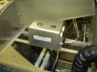
Things are starting to get back to normal. The wires are back in their places for the most part. I am starting to think about routing the wires to the engine, and I need to find a place for the Lightspeed ignition box.
The next thing I need to tackle, however, is the canopy. I've been putting this off for quite a while, but I think I need to get it done. |
 |
| Next: Avionics 2 |
|
| |
|
|