| |
|
Previous: Canopy |
|
| |
|
It is now mid-August and the summer heat here in Texas is beating me down once again. Now that I've finished the slider part of the canopy I can finally start to see a light at the end of the tunnel. Hopefully it's not attached to a locomotive. :-)
I am starting to contemplate taking this project to the airport within the next month or so. To that end, I have started to make a list of items that I feel need to be completed before moving it. Most of these tasks could be done at the hangar, but it is certainly more convenient to have the project in the garage, so I am trying to do as much as possible here before making the move. |
| |
|
8/15/05 - 8/16/05 - Aileron Trim - 6 hours
Picking off individual items will be the norm for the next few weeks, so my work will probably appear random. First on my list for no apparent reason is the electric aileron trim.
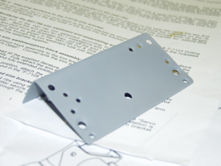
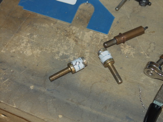
The servo mounts between and beneath the seats, and attaches to the controls via two springs. I promptly messed up the bracket when I mis-drilled the screw hole. So, I found a piece of .032 and made a new one. |
 |
| |
|
 |
 |
| |
|
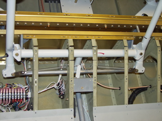
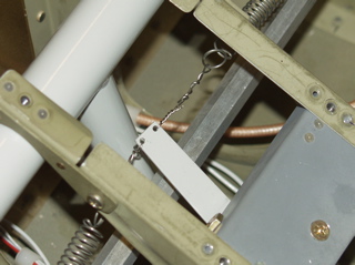
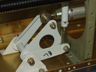
This was two nights worth of work. Probably because I'm slow. I had to go visit Radio Shack and buy a new terminal strip so I could attach the servo wires. I had already prewired for it, so all I had to do was attach the wires.
I think the most difficult part was attaching the hardware onto the stick weldments. There are tiny metal bushings that go on either side of the pushrod that are a real pain to get in place. |
 |
| |
|
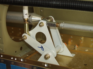
| The other weird part is trying to use safety wire to attach the bellcrank to the springs. My wires look terrible, but they are safe and secure. Maybe I'll try to redo them, but I am doubtful if I can do a better job the second time. |
 |
| |
|
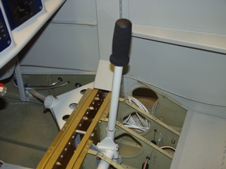
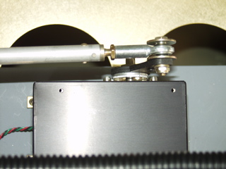
I also spent a little while attaching the stick grip to the passenger control stick. It has a ptt button on it that will attach via a mate-n-lok connector at the base. It may be too tall. I'll cut it down a bit later. The important thing is that it be removable so my passengers don't have to deal with it if they choose not to fly the plane.
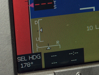
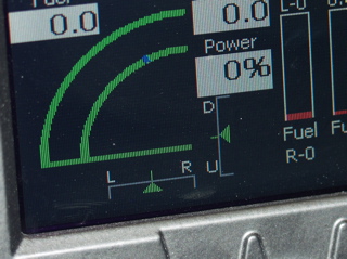
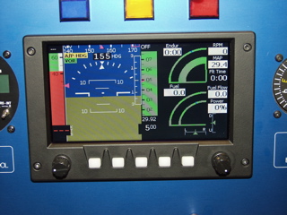
Finally, with both trim servos installed, here is what the trim indicators look like on the GRT EFIS. The left picture is the PFD, and the right picture shows the engine display. |
 |
| |
|
 |
 |
| |
|
| Here's a picture of the EFIS in split-screen mode. In this configuration, the trim indicators show up in the lower right corner. |
 |
| |
|
9/2/05 - 9/3/05 - Wing Stuff - 8 hours
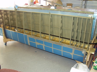
I didn't get a ton of work done over the weekend, but I did spend some quality time getting the wings in shape. The biggest concern I had was to make sure I have everything inside the wings that I need. So, here's what I have to hook up:
Left Wing: Pitot Tube, Lights
Right Wing: OAT Probe, Autopilot Servo, Lights
Lights are simple because I have installed conduit through the wings. The conduit is a pain to install, but now that it's in, it makes installing wires a no brainer. |
 |
| |
|
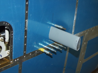
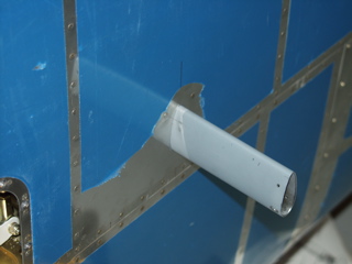
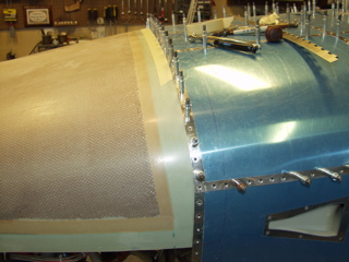
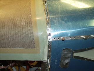
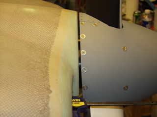
| The pitot tube is more of a challenge. I'm using a Dynon pitot tube because it's cheap and nice. I had bought this pitot mast from SafeAir1 a while back, so I had to cut a hole in the wing skin to accept the mast. |
 |
| |
|
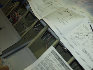
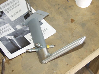
Here is the pitot tube installed in the mast. There are two aluminum tubes, but I'm only using one because I don't have the Dynon, so I can't use the AOA feature.
The pitot line goes in the wing after the wings are attached to the fuselage. Until then I will just install the mast, and leave the pitot tube off the wing.
Next, I assembled the big aileron tubes-the ones that connect the controls to the bellcranks. |
 |
| |
|
| Now for a step backwards. I decided that before I installed the lower wing skins that I would get all of the details worked out with the aileron bellcranks and push tubes and autopilot. Earlier I had assembled the aileron push tube, but when I assembled the ailerons to the wings and used the alignment tool, I found that the push tubes were just too long. So, I had to cut the end off of each push tube and order two new threaded inserts. This process is going to have to wait a few days. |
 |
| |
|
9/9/05 - 9/10/05 - Ailerons, Wings - 8 hours
This past week I had way too much real work to do, so I wasn't able to spend any time on the plane. I did, however, place an order with Van's for the replacement threaded inserts, so the first thing I worked on this weekend was the aileron pushtubes and the bellcranks. |
 |
| |
|
 |
 |
| |
|
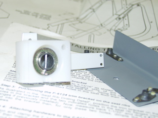
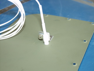
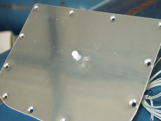
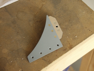
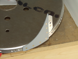
| Hey, I figured out how I was going to install the OAT probe. I decided to make a bracket and rivet it to one of the access panels, and then clip the OAT probe to the bracket and through a hole in the panel. This is going to work out great. Next I plan to install a mate-n-lok connector so I can still take the access panel off of the plane. |
| |
|
 |
 |
| |
|
| The rest of the time was spent riveting the bottom wing skins. I'm learning new ways to contort my body to try and reach the rivets inside the wings. Other than that, it's really not that difficult if you have a helper. I'm so glad to have a son who is willing to help me rivet. |
 |
| |
|
9/11/05 - Propeller - 2 hours
As many of you know, I have been waiting for my propeller I had ordered from Craig Catto. Craig had a family emergency last month, so my propeller was delayed by several weeks. Craig is a great guy to deal with and our prayers are with his daughter as she recovers.
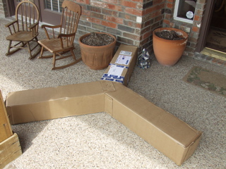
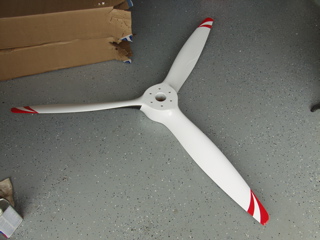
This morning look what showed up on my porch! Gee, I wonder what's inside?! I bet the mailman was curious. Anyways, the prop was very well packaged and it took me a good 10 minutes to get it unpacked. |
 |
| |
|
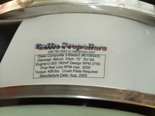
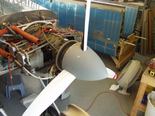
And there she is. Beauty. This is a wood composite prop. According to several people I've spoken to regarding props, these are the smoothest running props out there. They have all the advantages of a wood prop, but they are more durable and weather resistant due to all the layers of fiberglass. It's also painted with a nice coat of PPG Concept 2000 paint, which should protect it even further.
Yes, this is a fixed-pitch prop. I asked Craig to pitch it for cruise. He has a standard measurement for a -9A with an o-320, 160hp engine. |
 |
| |
|
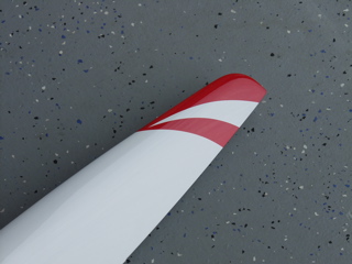
One interesting thing that I was not expecting was the cool propeller tip design that Craig did on my prop. This is different from the props shown on his site, and different from any that I have seen in person, but dang, it is totally cool looking.
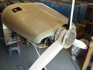
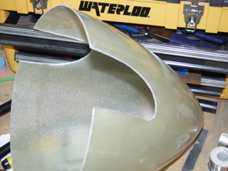
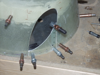
It didn't take me long to get busy putting this baby on my plane. The first thing to do was to make cutouts for each of the three blades on the flange of the forward bulkhead. This took several iterations, and I decided to be on the safe side and give more clearance rather than less. |
 |
| |
|
 |
 |
| |
|
So, here's the details: 66 inch diameter, 70 pitch. Designed to turn 2750 RPM on a 160hp O-320.
Yippee. Now I can fit the cowl. |
 |
| |
|
9/12/05 - Bottom Wing Skins - 1 hour
I spent another hour or so getting the last rivets done on the left wing. The left wing is now completely finished except for the tips. |
| |
|
9/13/05 - Right Wing - 1 hour
My rivet helpers are all doing homework this evening, so I did the best I could by myself. I got the easy rivets done, but quickly got stuck on a few that I couldn't reach, so I've decided to wait until later in the week. |
| |
|
9/14/05 - Spinner - 2 hours
Since I can't rivet the rest of the wing skins, I moved on to the cowl and spinner. I've decided to do the spinner first, since it will determine to some degree the location of the cowl.
I spoke with Craig Catto about the spinner, and he recommends moving the spinner until it touches the forward bulkhead, and leaving about 1/16" overhang past the aft bulkhead. This sounds reasonable, so I decided to proceed. |
| |
|
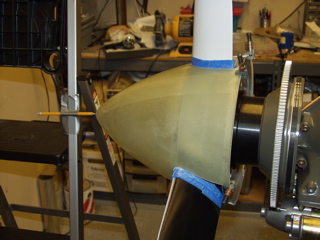
| A three-blade prop is a bit different than a standard two-blader, since there are an odd number of holes in the spinner. I started by measuring the circumference of the spinner with a piece of tape, and then divided it into thirds to come up with reference points for the three blades. Next, I made a cutout template from a piece of cardboard I got from a box of, what else, Mountain Dew! The template took some trial and error, but eventually I got a shape that fit the prop, so I transferred it to the spinner at the three reference points. I cut the spinner with a mini-cutoff wheel on my Dremel tool, and then I smoothed the edges with a drum sander chucked in my drill press. |
 |
| |
|
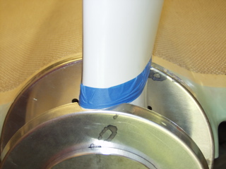
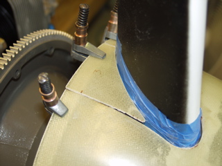
| I protected the prop with some masking tape before test fitting the spinner. The goal is to have between 1/16" and 1/8" of space between the spinner and the blade. Given that there are three blades, there is 3x the work. |
 |
| |
|
Here's the process: Mike sands a bit with the drum sander. Mike puts the spinner back on the plane. Mike makes some marks with a sharpie. Mike removes the spinner and does some more sanding. Wash, rinse, repeat.
I have decided to go ahead and put a ring of fiberglass around the inside of the spinner to build up the space for the forward bulkhead. It just isn't contacting the spinner like it should, and I don't want to trim the back of the spinner. |
 |
| |
|
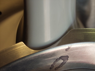
Before doing the fiberglass, I clamped the spinner in place with some cleco edge clamps. I set up a pencil like the instructions say. I removed the dessicant plugs from the top of the engine. The prop turns easily. Oops. Forgot about the oil. Now I'm cleaning up a big puddle of oil under the engine. This is the protective oil that Aerosport puts in the cylinders. The oil continues to drip as I play with the prop.
One thing I noticed is how noisy the magneto is. Whenever I bring the prop back to TDC, I hear a big click. Yes, the mag is grounded. Somebody smart can probably tell me, but I think this is the impulse coupling doing it's thing. |
 |
| |
|
9/15/05 - More Spinner Stuff - 2 hours
I went ahead and did a build-up of the inside of the spinner at the front bulkhead. I used two layers of 8oz bid cloth and some micro. The instructions say to do this using the bulkhead as a mold of sorts, but I didn't do it that way. I carefully drew some reference marks on the outside of the spinner, and then laid up the fiberglass along those lines (on the inside.) I did it in two stages, because I didn't want too much fiberglass. One layer wasn't enough, and two layers was a bit too much, so I ended up sanding it after the second layer. |
| |
|
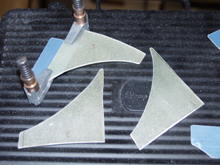
With that done, I re-aligned the spinner, did some more sanding of the blade openings, and then turned my attention to the gap fill pieces.
The plans say to use either aluminum or fiberglass. I was able to save the pieces that I had cut out of the spinner, so I matched them to their original openings, numbered them, and then cut them to rough shape. |
 |
| |
|
This is where they go. I spent a whole lot of time with the sanding drum trying to match the shape of the prop. Do this three times (for the three-blades) and you've spent a lot of tedious time.
I like the way these fiberglass ones have turned out. I think they will look good. |
 |
| |
|
9/16/05 - Spinner - 2 hours
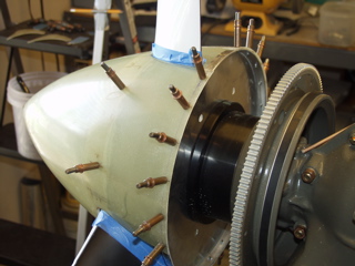
Tonight I did a lot of marking of the spinner to determine the locations of the screw holes. As this is a three-blade propeller, the standard screw count of 14 along the rear bulkhead didn't work, so I decided to use 15. The only problem is that I mis-counted when laying out the holes, so now I have 18. I guess the extra three screws isn't going to hurt anything. It just looks a bit more busy than it might otherwise look. |
 |
| |
|
Before and during this process I probably checked that the spinner was straight about 20 times. Turning the engine by hand released more of the protective oil each time, so I spent a good amount of time cleaning up the floor.
Next, I took the spinner and prop off the airplane and worked on getting the screw plates installed on the gap filler pieces. The gap fillers get riveted to the bulkhead, and the screw plate is riveted to the gap filler. Finally, a hole is drilled in the spinner to accept a screw, and a platenut is installed on the screw plate. I did all this three times. |
 |
| |
|
 |
 |
| |
|
9/17/05 - Spinner, cowl - 8 hours
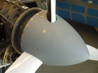
Yesterday I had drilled and countersunk all the holes in the spinner bulkheads, and countersunk the holes in the spinner itself. I had then taken the spinner, sanded it, and shot a coat of primer on it. Today, I finished this process by riveting the platenuts. That allowed me to reinstall the propeller and install the spinner with washers and screws.
I think it turned out nice. I was apprehensive about doing the spinner, but it turned out to be rather straightforward. |
 |
| |
|
 |
 |
| |
|
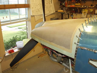
| Time to turn my attention to the cowl. The first thing was to cut the back of the cowl to rough size, using the reference line on the fuselage. I also cut and drilled the hinges along the top of the firewall to give the cowl a place to "rest." The instructions call for shimming between the hinge and the flange, but honestly I can't see that it is necessary, at least along the top. In my case, any shim would cause the cowl to sit lower than the skin, which would be bad. So, I clecoed the hinge in place without the shim. |
 |
| |
|
 |
 |
| |
|
| The instructions say that I need to leave the cowl a little lower than the spinner, to account for the engine eventually sagging. This is a bit difficult to plan for, since there is no way to know how much the engine will sag. I have read varying reports of people already flying. Some say that they wish they hadn't tried to account for sag at all, as their engine was still in the same place it was when it was installed. The other issue is that it is difficult to know how much extra space is going to be visible along the bottom of the spinner without first installing the lower cowl. |
 |
| |
|
 |
 |
| |
|
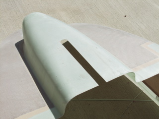
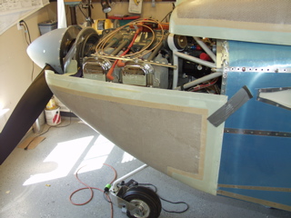
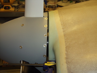
| In order to test-fit the lower cowl I first had to mark and cut a slot for the gear leg. Since mine is a three-blade prop, this slot is cut extra long, since the prop can't be turned completely out of the way as a two-blade prop is able to do. |
 |
| |
|
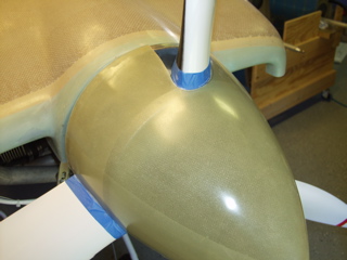
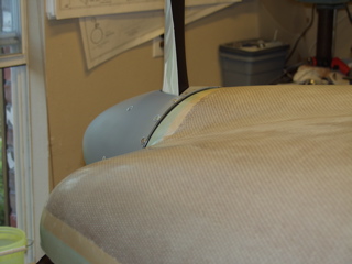
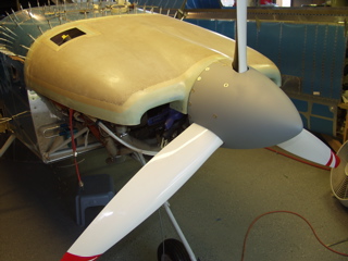
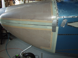
So, here's the lower cowl sort of taped in position, but without the top cowl. By doing this I noticed that there is more material around the spinner than I had initially anticipated, so I think the top cowl needs to be a little higher in respect to the spinner.
Side note: before there are any hinges attached to the cowl pieces, it is a real pain to try to hold them in position. I have tried using duct tape and clamps, but those methods are inexact at best. |
 |
| |
|
9/18/05 - More Cowl Work - 4 hours
After repositioning the top cowl higher in reference to the spinner, the cuts I had made ended up being too much, so I spent a while "grafting" a bit of fiberglass back onto the cowl to make up about 1/8".
The instructions say that I need between 1/8 and 3/8" space between the spinner and cowl. In a perfect world I would attempt to have about 1/4" of space all the way around the cowl. Unfortunately that's not gonna happen, as the shape of the cowl isn't lending itself to a nice equally spaced rim around the spinner. |
 |
| |
|
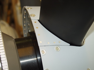
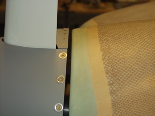
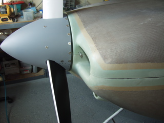
| This is the right side. It pretty good. The gap is larger at the bottom than the top, but remember we are accounting for a bit of engine sag here, so hopefully this will straighten out over time. |
 |
| |
|
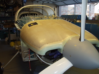
| This is the left side. It's not as good because of the angle of the engine. I've done the best I can to minimize the difference, but I think I'm going to give up on solving this issue with positioning, and rather fix it after the fact with a bit of fiberglass filler. |
 |
| |
|
9/19/05 - Cowl - 1 hour
I went ahead and drilled the hinges to the upper cowl where it attaches to the firewall. This at least gives some support while I work on the lower cowl.
Next, I trimmed the notched edge off of the lower cowl. The edge was not straight, so I'll have some work to do to get it to look good, but at least I can fit the two halves together. Yes, I remembered to leave the tabs around the spinner opening. |
 |
| |
|
The lower cowl is going to take some work to get it to fit nicely, as you can see. I need to cut along the bottom first to be able to see how well it fits along the seam on the upper cowl. Also, the front by the air inlets is sort of wacky, and will require some extra attention.
Next: More Misc. |
 |
| |
|