| |
|
Previous: Slider Frame |
|
| |
|
2/20/05 - Prep - 3 hours
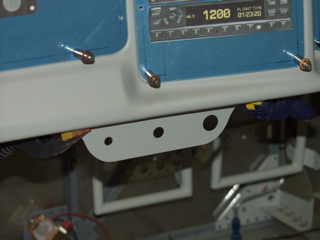
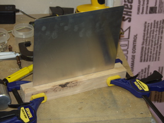
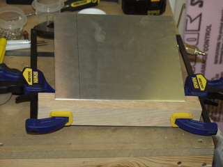
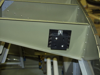
I know this isn't really electrical, but I needed to get this piece off my workbench, so I went ahead and installed it. I decided to just use screws and locknuts rather than bother with platenuts here since there is access to both sides without issue. So I marked and drilled four holes in the flange of the bracket. I measured to the center of the panel and drew a line on the inside. Then I measured the center of the control bracket and drew a line on the flange. Then I just matched up the lines, clamped, and match-drilled the bracket to the panel. |
 |
| |
|
 |
 |
| |
|
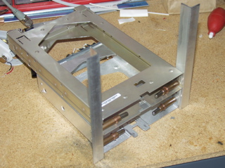
2/21/05 - Fuse Door - 4 hours
My electrical system is going to have three fuse blocks. All of which will be located behind the panel and I will not be attempting to mess with them in flight. However, once the front top skin is attached permanently to the fuselage there will be no easy way to access the fuses without crawling into the plane head-first and reaching up into the panel. So, after studying Andy Karmy's photos, I decided to install a hinged access door to the underside of the panel. |
 |
| |
|
The panel will be secured with a camloc under the passenger side of the instrument panel. To change fuses, all I will need to do is hop in the passenger seat and turn the camloc to drop the panel down.
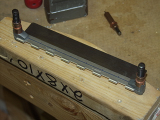
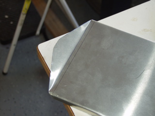
I started with some more borrowed aluminum, thanks to my friend Todd. I used some thin sheet to save on weight, and I bent flanges on the sides to strengthen it a bit. I used two pieces of oak as a simple break.
To save further on weight, I trimmed the corners a bit. |
 |
| |
|
 |
 |
| |
|
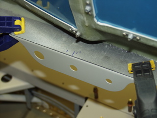
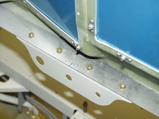
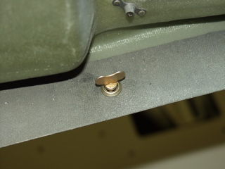
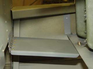
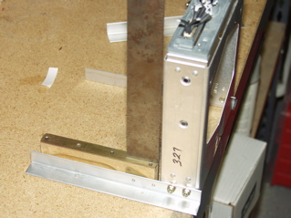
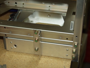
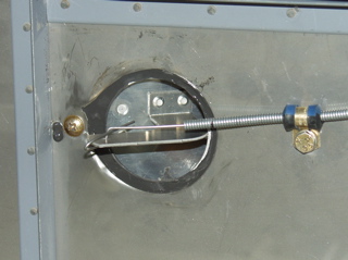
To locate the camloc, first I measured and drilled a 1/4" hole in the "trap door", then with it clecoed in place, I swung the door up to where it matched up with the panel. Then I simply match-drilled the 1/4" hole. I installed the camloc in reverse so I could match-drill the rivet holes for the "platenut".
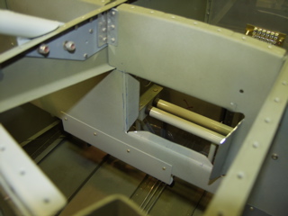
In the pictures below you can see the door installed. Notice that it slopes a bit due to the difference between the subpanel and the composite panel. That's why the lip of the door has a little bend in it, to match the angle of the panel flange so it sits flush when closed. |
 |
| |
|
 |
 |
| |
|
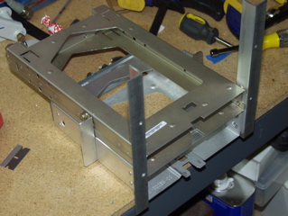
The previous picture was taken from the top. This should provide adequate "workspace" while installing all the wires, yet it is far enough out of the way that I don't think I will have trouble getting around it.
I'm really happy with this. I think it should make it easier to work on the plane later on. |
 |
| |
|
2/22/05 - Vents - 2 hours
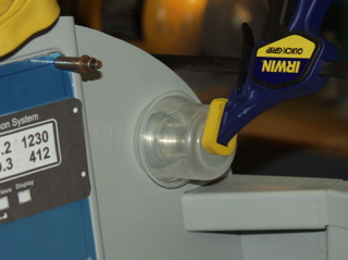
Okay, this is also not electrical, but I started to be concerned that my "fuse trap door" may interfere with the vent hoses, so I went ahead and installed the eyeball vents into the panel in preparation for routing the vent hoses. These vents are really nice, but they only had a tiny flange for attaching the hose, so I bought 2" flanges from Vans which I bolted to the eyeball vents on the back side. The whole assembly is then epoxied to the composite panel. Here you see my clamping method. I wanted consistent clamping pressure around the perimeter of the part, but I also wanted to be able to verify the alignment of the vent, so I used a see-thru jar. Worked great. |
 |
| |
|
| I also bought a set of Greenlee Slug-Buster punches off eBay. Not a cheap tool but one I need in order to install stuff to the firewall. Specifically I needed the 2" knockout punch so I can install the heat box to the firewall. I also plan to use the 2" punch to cut holes through the subpanel for the vent hoses. This will allow me to route the hoses where they don't interfere with the electrical stuff. |
| |
|
2/25/05 - Some Wiring - 6 hours
I had some help today from my dad, who drove up from Houston to give me a hand for a while. We went out to the airport and picked up my engine and brought it to the house. More on that later.
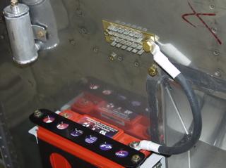
We started by making a ground wire. I referenced Bob Nuckolls' guide on attaching terminals to big wires. We used both a soldering gun and a small butane torch to get the terminal hot enough to suck in the solder. |
 |
| |
|
| You might notice the "extra" bolts in the firewall. These are to cover my most recent brain fart. I thought it might be better to tie the ground lug into the crossbeam to provide more support. Unfortunately, I soon figured out that the ground plate won't fit on the inside of the firewall if I do it that way. Remember that these tabs are on both sides of the firewall. Anyways, I moved up two inches and re-drilled. I figure I'll eventually need a hole there for something, but if not, there'll be an extra set of bolts along for the ride. |
 |
| |
|
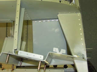
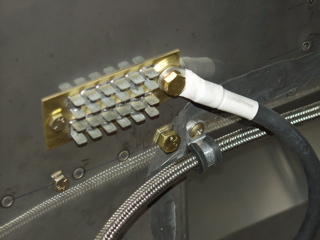
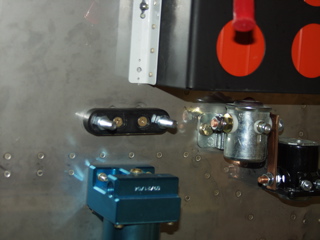
I also decided that now would be a good time to figure out the oil pressure line, so I went ahead and installed the fitting into the manifold and attached the line to the firewall using platenuts.
Next it was time to position some of the main electrical components. I installed platenuts on the voltage regulator so I could mount it to the back of the subpanel. This is in easy reach of all of the buses, and yet it is out of the way. I also installed the battery bus on one of the instrument panel supports. Here it is hopefully close enough to the battery. |
 |
| |
|
 |
 |
| |
|
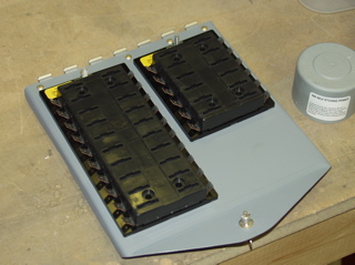
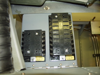
Here is a top view of the fuse blocks mounted to the "trap door" I discussed previously. The smaller block is the "Main" bus, and the larger one is the "E-Bus." I seriously doubt I will ever use all of the slots I have available. I think I have a total of about 22 circuits on the plane, and there are forty fuse locations in total on all three buses.
The trap door rocks! I have already taken advantage of it when I need to have better access. This was definitely time well spent. |
 |
| |
|
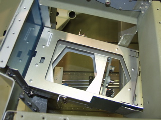
| Next I decided to tackle the avionics stack. I knew this would be somewhat tricky due to the odd angle of my fancy composite panel. I started by positioning the longest tray in the panel and marking where I thought the hole needed to be. I decided to bend flanges around the edge of the hole to be used as supports for the avionics. I did this by first drilling holes in each corner, and then drawing an "x" through the rectangle. I then drilled a second set of holes inset on the "x" to create a set of flanges. I then worked with my edge bending tool to bend the flanges. |
 |
| |
|
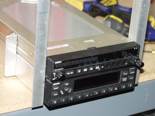
2/26/05 - Avionics Trays - 8 hours
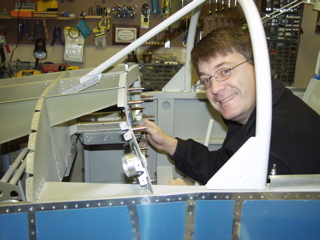
My dad shot this picture of me trying to get the radio stack to sit correctly in the panel. I was surprised at how far the radios stuck out of the front of the panel, so I kept working at it until I figured out that the radios pull back into the mounting tray about 1/4" when they are locked. I was glad to have at least one new radio so I got one of the little installation screwdrivers which let you install and remove the avionics. |
 |
| |
|
My dad had to leave mid-day, so I picked up working on the radio stack in the afternoon. I really wanted nice, straight radios in the panel, and with the funky angle of the panel I found that I was driving myself crazy trying to line everything up. I also found that the two radios have different types of trays, and it isn't enough just to line up the trays. Instead I had to install the radios to get an idea of where the trays needed to be so I could line up the fronts of the radios |
 |
| |
|
I finally decided that the only way I could achieve straightness was to use my "practice" parts to build everything up with a new set of angles, but do it outside of the plane.
Dan Checkoway mentions this on his site, but Garmin AT trays are a different width than the original Garmin trays. So I had to use tiny washers when I installed the SL-40 tray to make it match the width of the GTX-327. It wasn't a big deal since I had read about it on his site, but it sure adds to the time required to test fit it when you have to reinstall those washers some 30 times or so! |
 |
| |
|
One more thing about tray alignment. I found that I couldn't just stack the trays on top of each-other. I had to leave about .05" clearance between them so that the SL-40's little tightening bell would have enough room to swing down and latch. I did this by placing a piece of .063" aluminum sheet between the two trays during assembly.
I also fabricated some side angles to join the two trays and keep them from "scissoring" and moving the faces out of alignment. |
 |
| |
|
 |
 |
| |
|
| Back inside the plane, I reattached the new angles to the panel and then worked on the flanges that I had added to the subpanel. These provide great support for the back of the stack and I don't have to add any more metal to the plane. The hardest part was bending them in line with the holes I had drilled. On more than one occasion I found that the aluminum was starting to tear at the corners, so I had to use a dremel tool to releive the stress at those points by enlarging my corner holes. |
 |
| |
|
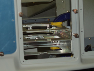
| Here's a picture of the almost finished setup viewed from the top. |
 |
| |
|
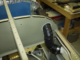
2/28/05 - Plumbing - 3 hours
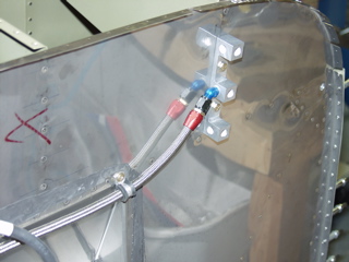
Yet another non-electrical item, but something that needs to be done so that I can know where to run the wires. Today I went ahead and ran the vent hoses from the NACA vents to the eyeballs on the panel. Van's supplies some 2" plastic vent tubing that is rather flexible, so I decided to go through the subpanel above the forward canopy decks.
I used a 2" Greenlee punch to make the pass-through hole. Much to my surprise, I quickly found out that a 2" conduit punch yields a hole that is about 2.3" in diameter. |
 |
| |
|
It turned out not to be an issue, but if tight tolerances are required, please double-check the tool before you use it. I bought some edge grommet material from Avery that I used to protect the edges of the big old holes that I punched. The hoses fit loosely in the new holes, so I will be securing them with tie-wraps most likely.
I went ahead and installed the hose clamps, but I'm not sure how to know when I have them tight enough. These things seem like they could squash the plastic NACA vent pretty easily. |
 |
| |
|
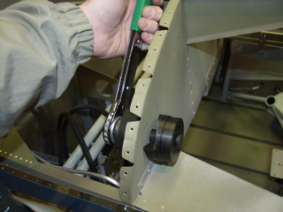
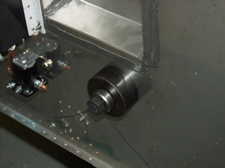
Next I went ahead and punched the hole for the heat selector using the same punch tool. This punch didn't seem to work quite as well on the stainless, and it left a little of the metal sort of crimped over on one side. I had to use some creative whacks with a hammer and a bucking bar to flatten it back out. In the end you won't be able to tell because the selector sits on top of it, but I feel rather snakebit when I try to do anything to this firewall.
Here's the selector in place. I went ahead and used ProSeal to seal it. I also went ahead and drilled the push-pull knob on the panel. |
 |
| |
|
 |
 |
| |
|
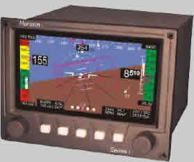
3/1/05 - Ordered EFIS
No work today, but I did place an order for my GRT EFIS and the EIS4000 engine monitor. I also ordered capacitive fuel senders and the fuel flow option. I ordered all this from SteinAir. Check out my Instrument Panel page for more details. |
 |
| |
|
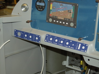
3/2/05 - Designed Switchplates - 3 hours
I spent quite a while measuring and re-measuring for my switch plates. I am using a company called Front Panel Express, and their software called Front Panel Designer. Although this service isn't cheap, the results are really nice. I had previously sent a sample panel piece, and it turned out great other than my poorly measured holes. So with that experience behind me I made these two panels, complete with countersunk screw holes! No need for a labelmaker with these beauties! Yes, they will be blue. |
 |
| |
|
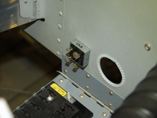
| The only other thing I was able to accomplish was to mount the bridge rectifier to the subpanel. I will really only be using one of the diodes in this package, but it is packaged in a convenient form factor for mounting in a plane. This device automatically provides power to the e-bus during normal operations. If the alternator ever fails, current will not flow back through it to the main bus, and all I will need to do is flip one switch on the panel to run the items on the e-bus directly off the battery. Check out the Aeroelectric Connection for more details. |
 |
| |
|
3/3/05 - Engine Crating, Heat - 3 hours
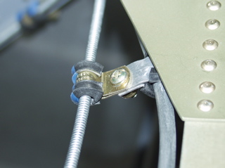
I spent a while doing some engine-related stuff, which I will explain on my engine page soon. After that, I finished installing the heat selector cable. I had been waiting on some adel clamps I had ordered from Wicks. These are nice and small, and fit tightly around cables.
I had seen somewhere that you can use two adel clamps to attach standoffs to aluminum tubing runs. Since I needed some support for the heat cable, I used the brake line to keep it from flopping around. |
 |
| |
|
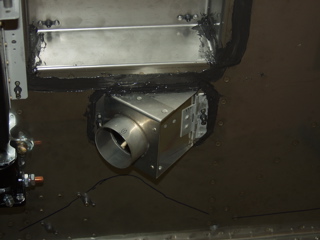
| Here is the completed vent. You might notice that there's a lot of ProSeal around the opening. That's because the punch was larger than the opening on the vent assembly. No worries, it is sealed up tight. Also, I had some trouble with the punch, and you might notice a little chunk missing from the left side of the hole. I did this because there was a little crack forming, and so I drilled a stop hole, and while I was at it I just cleaned up the crack by cutting around it. The ProSeal helps keep this all sealed up. I was pretty disgusted that I had messed up the hole, but now it's not even an issue. |
 |
| |
|
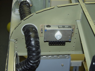
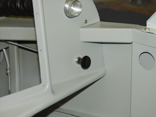
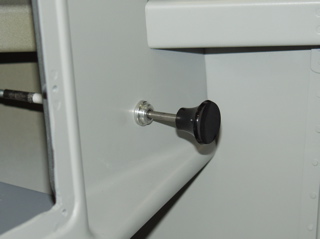
Here's the heat knob on the panel. This is what it looks like in the fully open position.
|
 |
| |
|
The last thing I did was to install the base for the ANL. I had ordered some #10 countersunk screws to install this to the firewall. They were in the Wicks order as well. Looking at this, I decided that I would install it with platenuts just in case, so I did the whole drilling and dimpling thing for the #10 platenuts.
The ANL needs to hook up to the starter contactor, so I guess I need to make a cable. |
 |
| |
|
| Finally, a big congratulations to my buddy Todd, who has taken the plunge this week and ordered his very own RV-10 kit! I guess his Sonex is a bit too small. I will be following his progress very carefully, since I would like to eventually build a -10 as well. |
| |
|