| |
|
Previous: Electrical Part Three |
|
| |
|
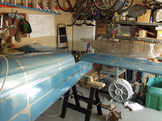
4/9/05 - HS, Elevators - 8 hours
I am at a crossroads on the electrical system. I can't wire any of the avionics until I receive the EFIS that I ordered. I am also waiting on a few other items which affect the wiring. I'd like to get the empennage installed and rigged so I can install the trim motor and the tail lights. It would also be nice to be able to say that the tail is all done.
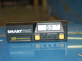
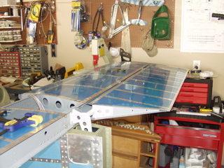
So, the first thing I did was to level the fuselage using my SmartTool. |
 |
| |
|
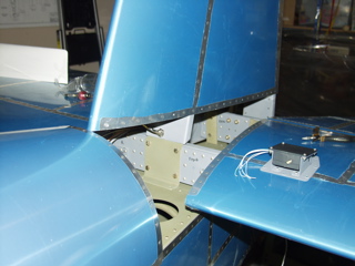
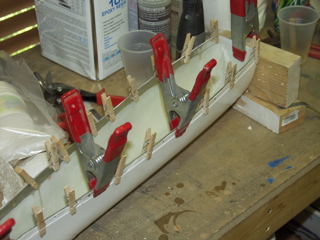
The next thing I did was to establish the squareness of the HS to the fuselage. I did this by measuring from the upper corners of the firewall to the center of the most outboard rivet on the HS spar. I went back and forth about a dozen times measuring first the left side and then the right side, making slight adjustments each time and then re-clamping it.
When I was finally satisfied that the HS was as perfect as I could make it, I went and re-read the instructions to make sure I was clear where the holes needed to go. I really didn't want to mess this up. |
 |
| |
|
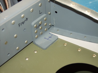
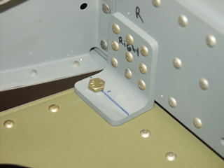
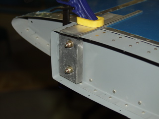
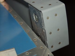
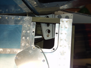
The outboard bolts need to go through the longeron. The important thing is to make sure there is adequate distance from the edge as well as from the vertical member, otherwise you will have trouble getting a nut on the bolt, which would not be good.
The longeron is 3/4" total, but 1/8" of that is occupied by the vertical member, so I drew lines on the angle bracket to define the "usable area" of the longeron. I must have measured this 10 times. I then drew a centerline in line with the rivets that are already positioned in the deck. This established the fore-aft position. |
 |
| |
|
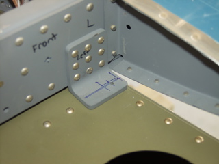
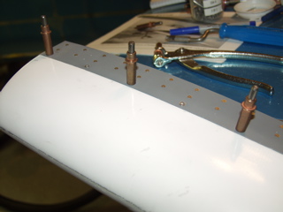
Next, I started adjusting for the thickness of the bolt and nut, and ended up with a position just a little forward of the existing rivets. When I was happy, I drilled a #40 hole, figuring I could move it slightly if it was wrong somehow. Nope, it was perfecto, so I enlarged the hole and inserted the AN3 bolt. I used this bolt as a pivot point, just in case it somehow got thrown out of whack when I was drilling it.
I went and measured the tips again to make sure they were the same, and then I re-clamped it in position. |
 |
| |
|
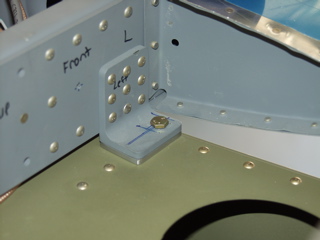
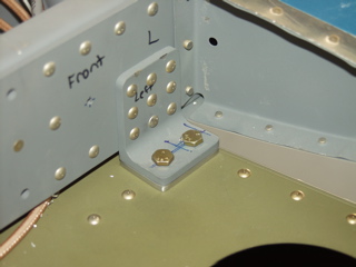
Same thing on the right side.
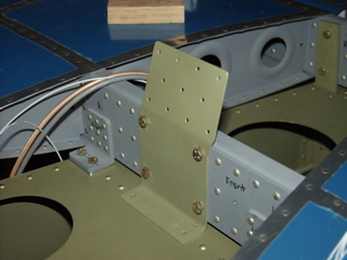
With these positions set, I went and fabricated the spacers according to the plans. These are made from aluminum bar stock, and need to be match-drilled after these first holes are done.
You notice that I didn't drill the inboard holes yet. This was so I could attach the spacer with the one hole, get everything aligned, and then drill the inboard hole perfectly through all of the material at once. This worked out great. |
 |
| |
|
 |
 |
| |
|
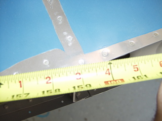
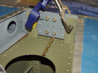
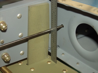
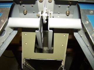
With the bolts in place it was time to turn my attention to the aft spar . The instructions call for a drill bit (7/16" I think, but don't quote me) to be placed under the aft spar to set the incidence.
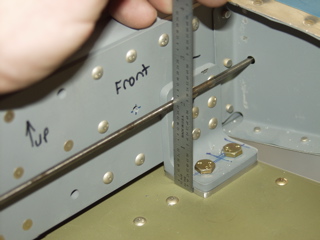
To verify it, they say to measure the tooling holes in the ribs to verify that they are the same. So, I put a 12" drill bit through the tooling holes and measured up from the deck.
Then I repeated this in the front. Perfect once again, so I continued. |
 |
| |
|
 |
 |
| |
|
| Did I mention the SmartTool? At every step I checked this thing to make sure the HS was still level. This isn't in the instructions, but I thought of it as a good backup, just to make sure I didn't goof somehow. Remember, we're dealing in three dimensions here, so this check is only somewhat useful, but it was nice nonetheless. |
 |
| |
|
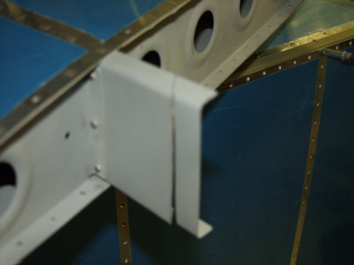
| There are no specifics as to where you are supposed to drill the bolt holes in the aft spar, so after studying the plans for quite a while I finally decided to use existing rivets as reference points. I left a little more space vertically so the nuts could clear the edge radius, so these are probably 1/2" from the inside edge of the flange. |
 |
| |
|
| With the HS firmly attached, I started working on the elevators. I had previously played with the rod end bearings to set the distance, but there was some more adjusting to do. |
 |
| |
|
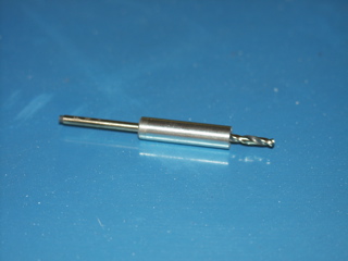
A few weeks ago I had ordered this bushing from McMaster-Carr. Van's calls for this to protect the bearing when drilling the elevator horns.
The process is to first get the elevator just where you want it, then put the bushing into the center bearing and, using a #40 drill bit, carefully drill the pivot hole through the control horn. Wash, rinse, repeat. Same deal for the left elevator.
After that, you take the elevators off and expand the hole to fit an AN4 bolt. |
 |
| |
|
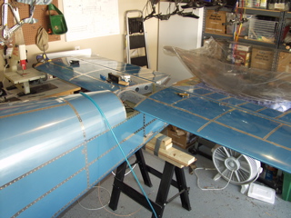
With both elevators reattached, I could get an idea of what I had ahead of me. With the elevator counterweights clamped to the HS, there was about 3/16" difference in the position of the trailing edges. This disturbed me a bit. I checked the angle with the SmartTool and determined that there's about 0.6° difference between the left and right elevators.
Understand that I have not yet drilled the all-important lower hole in the elevator control horns. I need to see if there's anything I can do about the difference. My best excuse for this is that there might be a slight twist in one of the elevators. |
 |
| |
|
4/10/05 - Elevator weights - 2 hours
I didn't get a whole lot done today, but I did manage to install the elevator counterweights. I started by cutting them to rough shape following the instructions on the plans. The instructions say to leave a little more material on the inside-left weight, austensibly to compensate for the weight of the trim actuator.
I used a variety of methods to get these to fit, but the best seems to be to shape it with a hammer. The material is soft. |
 |
| |
|
The tricky part was getting the inside weights to sit inside the skin so it wouldn't interfere with the motion of the elevator.
I still have some trimming and balancing to do. |
 |
| |
|
| 4/14/05 - 4/17/05 - Sun N Fun (Click here for details) |
| |
|
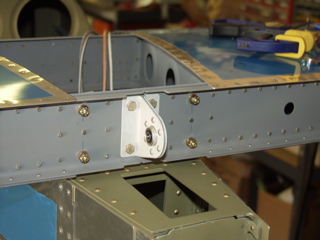
4/19/05 - Vertical Stabilizer - 1 hour
It's good to be back working on the project again. Trouble is, there's so much I could work on that it's difficult to pick something. So, I am going to continue working on the empennage.
I located and attached the F-981 VS attach bracket and match-drilled it to the fuselage. I had prepped and primed this part a long time ago, but up until now I really didn't know where it went. |
 |
| |
|
The forward spar of the vertical stabilizer needs to be trimmed according to the plans. I marked the location and then made the cut with my cutoff wheel in the die grinder, followed by some deburring with a new Scotchbrite wheel I got at Sun N Fun.
As I look at the plans, it appears that the forward spar of the VS attaches to the front of the F-981, but I need to verify before I match-drill. |
 |
| |
|
 |
 |
| |
|
Engine Update: Sue from AeroSport called Monday and told me the engine would ship today. So, if everything goes as planned, I should receive my engine by the end of next week!
Also, I've been deliberating about how to drill the hole in the elevator horns. I have finally decided to do the following:
- Measure the distance between the horns and make a block of wood that fits snugly between them.
- Take the left elevator off the plane and drill the hole according to the plans.
- Drill a matching hole in the wood block, using my drill press to make it nice and straight.
- Reattach the left elevator and clamp the block in place.
- Match-drill the right elevator horn.
- Enlarge the holes to full size.
- Remove the spacer block and install the bolt.
This may seem obvious, but it took me a while to visualize exactly what Vans wants me to do to get these things drilled properly. Hopefully I can tackle this on Wednesday. |
| |
|
4/20/05 - Elevator Horns, Pushrod - 2 hours
The horns are about 0.7" apart, but they taper inward slightly, so that measurement is a bit suspect. So, I went and found a piece of wood that was 0.71" thick and cut a small block (about 1.5" x 3") to use as a guide.
I removed the right elevator since it is more aft than the left one. Then I measured and drilled a #30 hole in the horn at the correct location according to the plans. |
 |
| |
|
| Next, I reinstalled the right elevator. I drilled a #30 hole in my guide block and then inserted it between the horns. I used a #30 pin punch to line up the hole in the right elevator horn with the hole in the guide block, then I clamped the block securely. |
 |
| |
|
With the guide block in place, I match-drilled the left elevator horn, then I enlarged each hole to final size. This really wasn't all that difficult after all. I guess I was just apprehensive because it affects the control and rigging of the plane.
Now I need the pushrod, so I found the right page of the instructions and located the parts. I prepped and primed the pushrod tube, but in hindsight I sort of wish I had just left it alone, because after all the fussing with the ends I scuffed up the primer. I guess I'm going to need to touch it up when I'm done. |
 |
| |
|
The ends were a tight fit. I had to use a rubber mallet to coax them into position, and after drilling they wouldn't come out, so I did my best to clean up the holes and then I installed the pop-rivets.
Hopefully tomorrow I can install the pushrod and get back to installing the Vertical Stabilizer. I ordered some more fiberglass supplies so I can start on the empennage tips. Jim Smith is doing a good job documenting his efforts, so I might finally get mine done. |
 |
| |
|
4/21/05 - Static port, Pushtube, Trim wiring - 4 hours
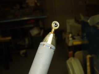
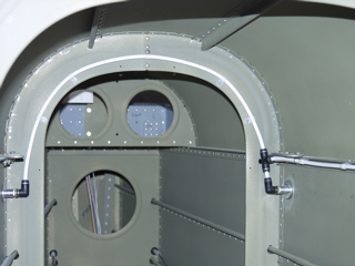
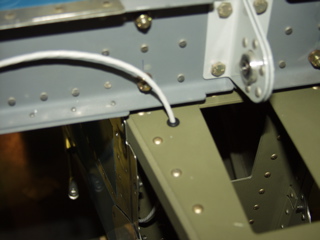
One thing I've been needing to do, but that I have put off, is the modification of my static port installation. Initially I had attached the feed line to the center of the arc between the two ports. I have had several people email and tell me that this is a bad idea, including Tony from SafeAir1. It has something to do with moisture and pressure differential, which I don't fully understand, but I'll fix it anyways. So, before messing with the elevator push tube, I decided to climb back into the tailcone and modify the setup. |
 |
| |
|
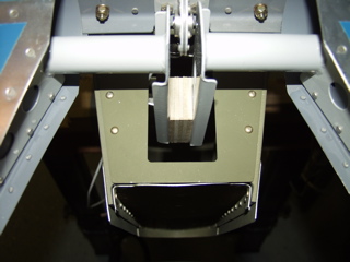
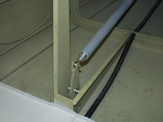
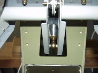
With the static line fixed, I installed the elevator pushtube and temporarily pinned it to the bellcrank. I went ahead and bolted it to the elevator horns to make sure everything fit correctly.
I made some adjustments to the length in order to get the bellcrank to stand straight up in neutral position. I also had to go back and adjust the forward pushrod to get the control sticks to be straight.
After a bit of fiddling I removed the pushtube. The elevator counterweights still need to be trimmed. |
 |
| |
|
 |
 |
| |
|
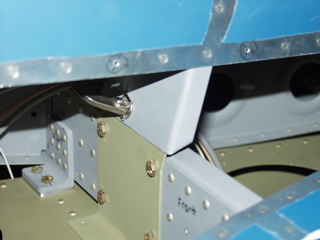
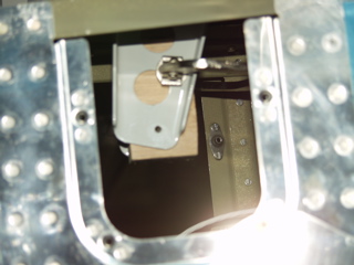
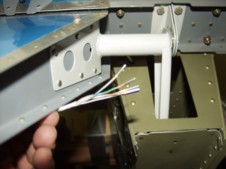
| The remainder of my evening was spent (wasted) trying to figure out how I was going to route the trim cable for the elevator trim servo. Here's the problem: I don't want the trim cable to interfere with the controls, but in order to connect to the servo it needs to be attached to the elevator. If it sounds like a contradiction, then you understand my dilemma. After probably two hours of deliberation, I finally decided to run the cable through the bulkhead and aft of the HS rear spar, and then I punched a hole through the aft deck. I will attach the wire to the elevator control horn with a tie wrap. |
 |
| |
|
The wire then goes inside the elevator and through the snap bushing where it attaches to the servo.
I'm using the Checkoway method of attaching the trim servo, using d-sub pins and sockets to connect the wires. These will be shrink-wrapped when the elevator is installed for good. If I need to remove the elevator, the shrink wrap can be cut open and the wires will easily disconnect. |
 |
| |
|
4/23/05 - Tips, Fish Fry - 4 hours
I decided to go ahead and install the fiberglass tips, so earlier in the week I ordered some supplies from Spruce like microballoons, peel ply, and primer. Today I finally started working on the first one. The process starts by trimming the excess material from the tip so that it will fit. I used the highly scientific trial-and-error method, using the rotary cutter in my die grinder to grind away the excess until it sat flush with the aluminum. |
 |
| |
|
I soon figured out that I needed to heat it and expand the opening so it would adequately fill the end of the elevator. I did this with the heat-shrink gun, and other than almost burning my fingers off, it worked great. The process is to heat the part and then hold it in the new shape while it cools.
I decided to go ahead and install some aluminum strips behind the joint to provide the pop rivets with a more solid connection. I used some .025 alclad cut in 1/2" strips. I epoxied these in place with T88 and left them to cure. |
 |
| |
|
 |
 |
| |
|
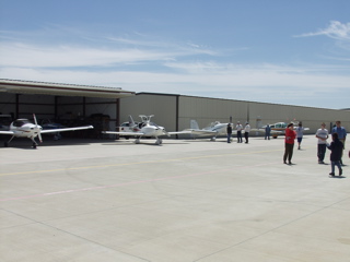
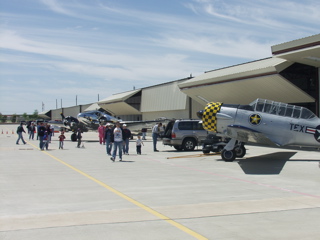
| Today was also the EAA Chapter 1246 annual Fish Fry out at TKI (McKinney) airport. We had a great turnout due partly to the great weather no doubt. We had a good number of planes fly in, and probably 200 or more people eating lunch. I ran into Jim Smith who is building an RV-7A. I also snapped some photos of Tom Moore's RV-7A slider, hoping to get a better grasp of what I have to do. I also was able to borrow an engine hoist from Tom Ferraro. |
| |
|
 |
 |
| |
|
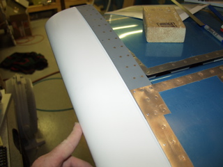
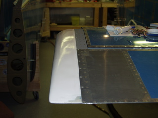
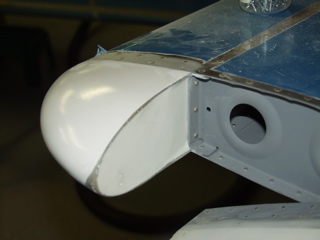
Back to work. I drilled and countersunk the tip, and I dimpled the skin. Then I removed a little material from the dimples using my deburring tool. This helped the pop rivets sit better in the dimples. I riveted every other hole, and then went back and replaced the remaining clecoes with rivets.
The results look pretty good, but not good enough. What you can't see in the pictures are a lot the imperfections. I suppose I could leave it like this, but I think I can improve it with a little work. We'll see. |
 |
| |
|
 |
 |
| |
|
4/24/05 - Tips - 2 hours
I mixed up some epoxy resin with microballoons and spread a thin layer on the joint. This is the first time I've used this stuff, so I didn't quite know what to expect. It is definitely lightweight. It also spreads very nicely. When left alone it levels itself. I may have used a bit too much, but it's my first try, so I'll get better. |
 |
| |
|
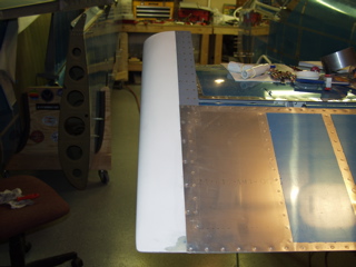
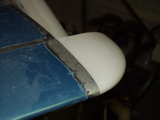
After allowing it to get nice and hard I attacked it with the sander. Yes, this looks ugly, but it is much more smooth overall than before. By the time I am finished you won't be able to tell where the aluminum ends and the fiberglass begins.
The remainder of my time was spent putting little metal strips inside the HS tip. |
 |
| |
|
4/25/05 - Tips - 2 hours
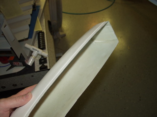
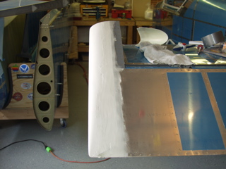
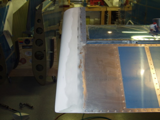
Still working on the left side, I started working on the Horizontal Stabilizer tip. This piece goes in front of the elevator counterbalance arm but is attached to the HS.
The tricky part about this piece is that the back side is open, and the instructions tell you to fill it with one of several methods. I chose the "sandwich" method, where a piece of balsa wood is used as a rib, and then fiberglass is laid up on either side of it, permanently encasing the rib (which has no structural value) in the fiberglass. |
 |
| |
|
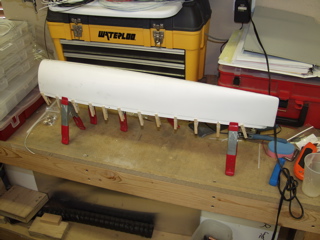
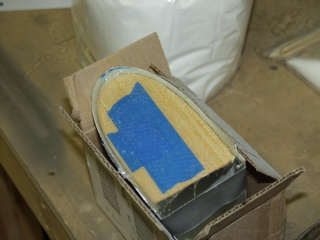
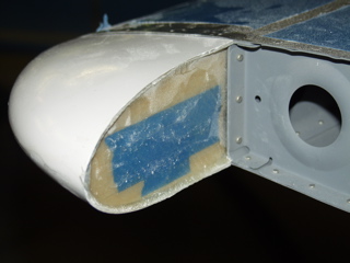
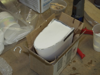
I used a small box to hold the piece secure while I laid up the fiberglass.
Here's what it looks like after everything set up overnight. The blue is some masking tape I used when the balsa wood cracked. The next step is to fill it with microballoons so it can be shaped to match the end of the elevator counterbalance arm.
If you think this looks more like art class than airplane building, you're right. |
 |
| |
|
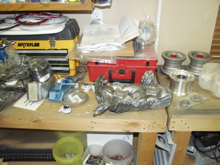
| Getting tired of fiberglass, I decided to open up the box containing the wheels and brakes. I need to install these soon so I will be ready to hang the engine. Man, there are lots of parts that I'm not sure how to assemble. I guess it's time to start reading the instructions again. I can remember while working on the wings that I was amazed when someone who was nearly finished with their plane confessed that they hadn't looked at the instructions in months. Now I am starting to understand, because there's really nothing in the instructions that can help you with most of these steps. Hopefully I can find something about wheel installation on the web. |
 |
| |
|
Oh, and I almost forgot. I ordered my autopilot today. I decided to go with the Trio EZ-Pilot. I spoke with both TruTrak and Trio at Sun N Fun, and although lots of people like the TruTrak, their basic wing-leveling autopilot was just a bit too basic for me. The Trio has the ability to follow a flight plan from my GPS or EFIS, can intercept a course, and can do an automatic 180° course reversal. Additionally, it is not dependent on GPS data. It has a built-in electronic mems-gyro. This means that it can serve as a standalone backup in the case of an emergency.
I also like the way they have integrated a stick button which allows the pilot to disengage the autopilot by pressing a button on the control stick, and the pilot can make minor course adjustments by holding the stick button and "flying" to a new heading. When the stick button is released, the autopilot will then stay on the new heading.
The display is also much more useful than the TruTrak. I don't really understand the Pictorial Pilot. I guess it serves as a way to visualize your attitude in one dimension, but I'd rather have the extra information that I can get on the EZ-Pilot. It can display GPS steering data, flight time, a turn coordinator, and other stuff that I'm just learning about.
Bottom line is that this is a great autopilot for not a lot of money. It serves as a practical backup to other instruments in the event of accidental IFR. Check it out. Call the guys at SafeAir1. They have also developed the mounting hardware for the RVs, and they'd be glad to sell you on it I'm sure. |
| |
|
4/26/05 - Tips - 2 hours
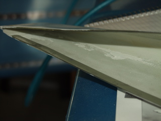
Back to the fiberglass. It is hard to do more than about two hours of work at a time on this stuff because eventually you have to wait for the epoxy to cure. So, today I went out in the morning and mixed up some micro and filled the end of the HS tip. By evening it had set up nicely, so I cleaned it up and installed it in the HS. After sanding it a while it's starting to look pretty good. |
 |
| |
|
 |
 |
| |
|
| Onward to the right side. I drilled and clecoed the tip in place and quickly noticed that the same phenomenon was happening with this side that I saw on the left side. The counterbalance arm was being bent inward by the force of the fiberglass tip as I clamped it into alignment with the predefined edge. So, I decided on this side that since I am filling and glassing the joint anyways, that I'd rather have a straight counterbalance arm, so when I enlarged the holes to #30, I allowed them to float a bit, enabling the arm to straighten out. This is far better in my opinion than trying to shave the inside of the counterbalance arm. |
 |
| |
|
| Next: More Empennage, and the Landing Gear |
| |
|