| |
|
Previous: Attaching the Empennage |
|
| |
|
4/27/05 - Fiberglass - 1 hour
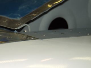
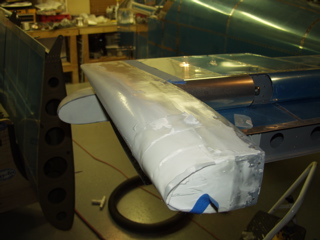
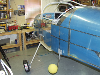
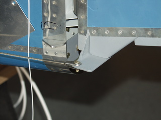
With the tips attached it is really tempting to just move on and leave them alone, but if you look at the picture you can see (maybe) the gaps that are present between the fiberglass and the aluminum. So, that's why I'm spending the extra time with the fiberglass right now. I figure any work done now is work I won't have to do when I go get it painted later on. |
 |
| |
|
| So, once again with the right side I started filling with microballoons. This time I decided to use some of the peel-ply that I bought to see if it makes any difference. My conclusion is that the peel ply works better when you are doing a fiberglass layup than when you're just filling. |
 |
| |
|
4/28/05 - Right HS Tip - 1 hour
It's difficult to get much done in one stretch with this epoxy having to cure, so these days I am lucky to get two hours in before I give up. Tonight I drilled the tip for the right side of the HS. I cut strips of aluminum and mounted them to the inside of the flange using T88 epoxy. |
 |
| |
|
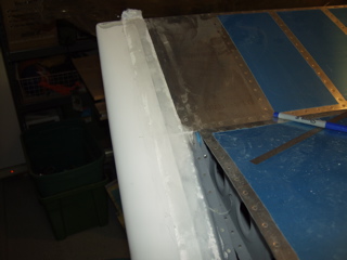
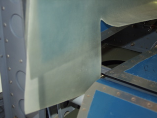
| Here's the left side after filling the end of the tip, but before any sanding. It is a nice 3/16" (roughly) gap between the HS tip and the elevator tip. I need to build up the elevator tip to match the profile of the HS tip in front of it, but I don't think that will be too difficult. |
 |
| |
|
4/30/05 - Filler, Wheels - 8 hours
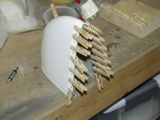
I finally have a full day I can work on the plane. I start by attacking the elevator tips. I globbed on a bunch of micro along the tip of the left elevator tip to try to get it closer to the profile of the HS tip. I used peel ply to hold the filler in place while it cured.
Today was quite a bit cooler than the past few days, and the epoxy was noticeably slower in curing. The other day with 85+ degrees, the epoxy started to cure almost immediately, but today it was in the low 70s. |
 |
| |
|
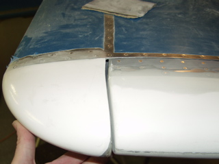
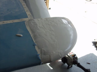
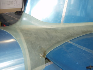
| Next, I put a coat of filler along the gap of the HS tip. This will mostly get sanded off, but doing it this way eliminates any valleys along the attachment line. |
 |
| |
|
With the epoxy hardening (slowly) it's time to switch gears. I need to get the landing gear assembled so that I can hang the engine when it arrives. So, I collected the parts I thought were related to the undercarriage, and started reading the instructions once again.
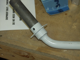
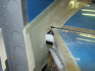
The first thing I did was to install (and drill) the mounting flange. The holes are already there, but they are undersized, so I had to run a 5/16" bit through them. |
 |
| |
|
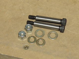
| Next I had to hunt down some hardware. These are allen head bolts with coarse threads on the very ends. They go through the axle and hold the mounting flange in place. The allen head is installed from the front and the bolts to the rear. To avoid making two left sides, I physically placed the left gear on the left side of the plane, and the right gear on the right side. |
 |
| |
|
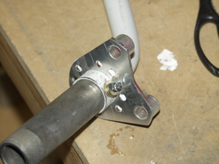
| This is just a test fit of the hardware. There is a brake mounting plate that needs to go in between the flange and the bolt, so all this came back out a few seconds after I snapped the picture. |
 |
| |
|
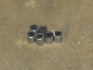
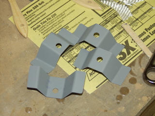
| I spent way too much time making these little guys. They are spacers for the wheel pant mounting plate. The interesting thing is that if you make these to the dimensions spelled out on the plans, you will need to add a washer to get the right clearance. It even says to do so on the instructions. Fortunately, I made mine about 1/32" longer than it calls for, thinking that I could grind them down to final length. When I finally assembled everything, the gap was perfect without any additional spacer required. So, if you are getting ready to make these, my advice is to leave them long. |
 |
| |
|
Now comes the confusing part (to me at least). The Cleaveland brakes that Vans supplies include a mounting bracket. Unfortunately, there are no instructions included with these. The instructions from Vans says to attach the mounting plate, but gives no hint as to exactly how you go about this. They do say that brakes are installed with the caliper to the rear and the bleed nipple facing down, but that's about it. I guess I'm an idiot, but it wasn't obvious to me how these went together. So, after a bit of web surfing I finally gathered enough info to start playing. |
 |
| |
|
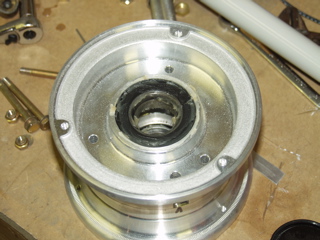
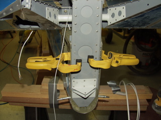
The brakc bracket wouldn't fit around the mounting flange until I polished the inside of the hole with a scotchbrite wheel.
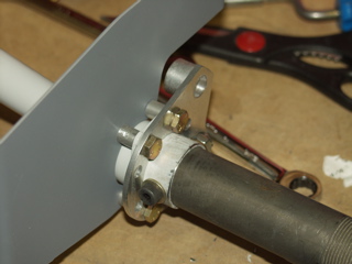
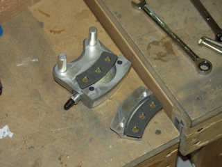
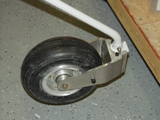
You want to put the "ears" of the brake bracket to the rear, with the extrusions facing in towards the plane, like you see in the picture above. The wheel pant attachment bracket (which I scuffed and primed) is attached with the bolts facing in towards the plane, with the spacers on the inside of the mounting flange. |
 |
| |
|
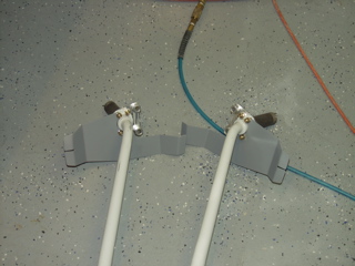
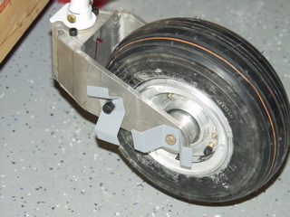
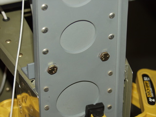
| With that much figured out, I duplicated it in reverse for the right side. Notice that the wheel pant brackets have their flanges facing in towards the plane as well. |
 |
| |
|
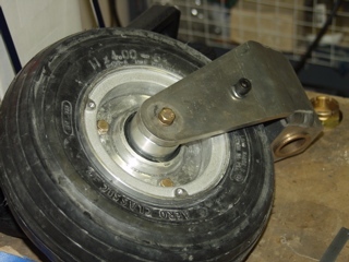
Next come the brakes themselves. Here we go again with my total lack of knowledge about brakes and wheels, so back to the web I went for more education. The instructions say to remove the outboard brake pad and "bolt" the brake to the mounting plate. Right. What's a cubit?! There are only the two pins on the caliper, and they don't have any threads. How am I supposed to bolt it to the bracket?! After fiddling with the brakes for a while I figured out that the thru-bolts can be removed, allowing the outside brake pad to be taken off (like you see in the picture.) This allows the big part of the brake caliper to be slid into place on the mounting bracket. Now I am starting to understand. These brake calipers "float." They are not bolted to the bracket like the instructions say, but rather the "rotor" on the wheel is "captured between the two brake pads, which keep the brake pad from falling off the plane. |
 |
| |
|
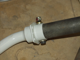
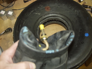
| Time to detour into wheel assembly for a while. This is a bad picture but I wanted to show the "hardware" that is included on the tube's valve stem. As best as I can figure, all of this hardware is discarded except for the cap. There is a rubber grommet in the wheel itself, and the hardware doesn't seem to be required. I'll have to check on this to be sure. |
 |
| |
|
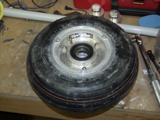
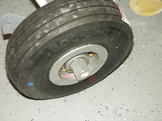
The wheel assemblies went together pretty easily. I checked the bearings and the bearings on these main wheels were fully packed with grease, so I didn't add any more.
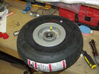
The valve stem is to be lined up with the red dot on the tire (not the pink dot or the blue dot). There are many warnings to be careful not to pinch the tube when assembling the wheel, but when I installed my tube and partially inflated it prior to installing the wheel halves, the tube wasn't even visible around the tire opening. Better safe than sorry, I guess. Anyways, the wheel was assembled and the bolts were torqued. |
 |
| |
|
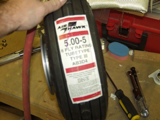
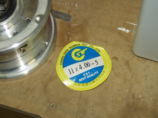
| After slowly inflating and deflating the tire to 25psi a couple of times, I was pretty confident that it was holding air. This is a picture of the label in case I need to replace it later and I can't locate the data any other way... |
 |
| |
|
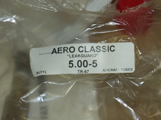
...and here is the tube information.
If I'm ever stranded in timbuktu and I have problems, maybe I can access this site via the global internet and be able to figure out what part I need replace a tire. I've been following the story of Bill Randolph as he attempts an around-the-world trip in his RV-8. http://www.eaa119.org/ |
 |
| |
|
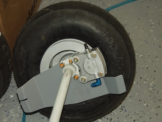
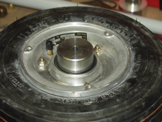
This picture shows the completed assembly, but the whole mess is rotated upside-down, since it is resting on the floor. The bleed nipple will normally be at the bottom, and the wheel pant mounting plate will be at the top.
I got both main gear done today. Next, I will attack the nose gear, and then I can put this puppy up on it's own three feet! |
 |
| |
|
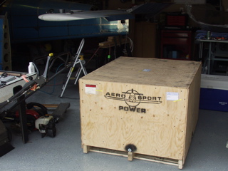
5/3/05 - The Engine Arrived
I spent the short amount of time that I had available today inspecting the totally beautiful engine that I received back from Aerosport Power. Check out the Engine page for more details.
I did spend a little bit of time in the late evening trying to get the nosewheel on the hub. About the only thing I did was to destroy one of the two tubes they send, and to get baby powder all over myself. |
 |
| |
|
5/10/05 - Nosegear - 6 hours
It has been one of those weeks where I'm totally chained to the computer, so any time that I have had to work on the plane has come in such short segments that I have not been able to write them up on the site, so here is a summary of what I've accomplished over the past week.
I assembled the nosegear. Fortunately, Van's has the foresight to send me two tubes, because I totally ruined the first one. All I can say is to make sure you hear metal on metal before you tighten the bolts. :-( |
 |
| |
|
 |
 |
| |
|
I looked for a bearing packer tool at several stores with no success, so finally I just got my hands all greasy and did it the old-fashioned way. The nosegear bearings are now packed with grease.
Here's one of the little axel things installed. The whole assembly is then squeezed into the fork of the nosegear attachment thingy (sorry, I don't know the real name for it.) |
 |
| |
|
 |
 |
| |
|
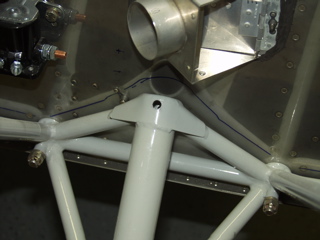
| Time to attach the nosegear to the engine mount. I had to cut a hole through the firewall to allow access to the back side of the attachment bolt. This required the engine mount to be removed. Hopefully this is the last time it needs to come off, because when I reattached it, I went ahead and torqued and sealed the nuts. When I went looking for the cotter pins, however, I couldn't find them, so I have some on order from Spruce. |
 |
| |
|
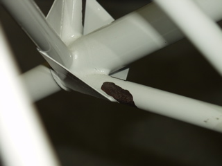
I noticed some cracking in the powdercoat, so I flaked it away as best I could, cleaned it up, and shot some primer on the affected areas.
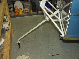
Next came attaching the fork to the leg. This thing does not go on very easily. Additionally, I needed a 1 1/2" box wrench or socket to be abe to tighten the bolt, which I didn't have. So, I eventually went to Home Depot and bot a big crescent wrench, since that was all they had. Next time I'm at Harbor Freight I'll pick up a big, cheap, socket. |
 |
| |
|
 |
 |
| |
|
| I went ahead and attached the brackets that hold the wheel pants in place. I don't know if I will have the pants on for first flight (probably not), but I wanted to get these done. |
 |
| |
|
| This next operation is tricky, and I didn't have my camera around for the pictures, which is probably good because there's lots of frustration involved. Basically you have to drill a hole through the axle to accept a cotter pin that holds the axle nut in place. To make it difficult, the nut already has the holes drilled, so you have to drill the axle using the holes in the nut as guides. Unfortunately, you can't drill it with the wheel in place, so you have to mark the spot, remove the wheel, and then drill the holes. I say holes because you can't just drill straight through the axle. After drilling the top hole, I used the nut to find the opposite hole on the bottom, and then drilled it from the bottom. |
 |
| |
|
The axle is made of steel, which is a pain to drill. To complicate things even further, you must be careful not to damage the threads. The nut is made of Aluminum, and its threads will not hold up to damaged threads on the axle. Additionally, you must make sure the wheel still turns freely.
Well, I finally got everything done, and the cotter pins installed. I haven't yet bent them over just in case I need to take the wheels off.
Oh, during all this, I've been filling and sanding the fiberglass on the empennage tips. |
 |
| |
|
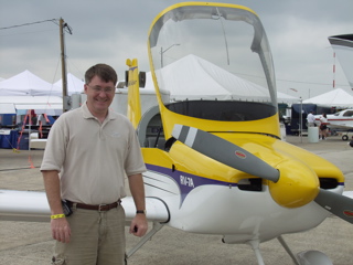
5/13/05 - SWRFI
I finally got to ride in an RV. I have been to probably five fly-ins with no success. So this time I was determined that I was going to get a demo flight. I got to Vans booth early on Friday and was the first person on the list. Now all I had to do was wait until 4pm.
Wow. I gotta get me one of these. I flew in the factory 7A. I liked it a lot. I can see how I might get addicted to flying something like this. Mine will be a bit different, but it was still great to fly. |
 |
| |
|
5/15/05 - Tinkering - 2 hours
With my demo flight fresh in my mind, I tried to get busy finishing my plane. Unfortunately I had lots of interruptions, so there wasn't a lot of progress. I did manage to fabricate the elevator stop bar.
|
 |
| |
|
I cut the bar stock and marked it for holes. Then I sprayed a bit of primer on it and I was ready for rivets. |
 |
| |
|
5/17/05 - VS - 2 hours
Time to mount the vertical stabilizer. First I clamped it in position along the back side of the F-912 bulkhead. The instructions say to measure it from the tip to each tip of the HS, but I measured from either side of the top of the main VS spar because the "tip" is difficult to determine exactly, since it is round.
|
 |
| |
|
| Once I was sure that it was vertical, I drilled the two bolt holes through the VS spar and the elevator stop. Actually I backdrilled, since I had already put pilot holes in the elevator stop. These bolts are inserted facing forward. |
 |
| |
|
The instructions say to make sure the VS is vertical, and either attach it to the front or the back of the forward bracket, based on the way it fits. Mine seemed to fit well being attached to the front of the bracket (bracket inside the spar) so that's how I did mine.
I match-drilled the holes in the forward spar and drilled the holes for the lower bolts. The instructions talk about installing the tiedown bar, but I had done this back when everything was apart, and I think I'm glad I did, because access would be quite a pain at this point. |
 |
| |
|
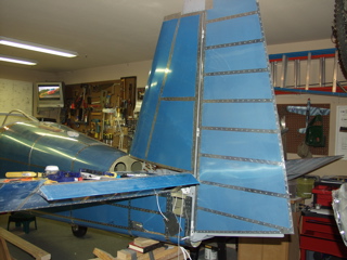
| With everything temporarily bolted in position, I attached the rudder. I have some tweaking to do, but it looks good. |
 |
| |
|
5/18/05 - Rudder Stops - 2 hours
It's been a while since I've had to fabricate a part, so this was fun for a change. I had skipped these when they were initially mentioned in the instructions, but now I'm back to them because they need to be installed permanently.
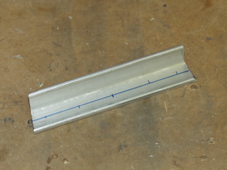
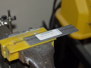
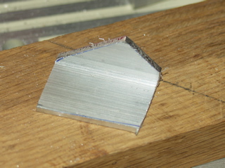
The cheap bandsaw blades I get at Harbor Freight don't seem to last very long, and the current one is getting really dull, but I did manage to cut the two rudder stops from this piece of angle without hurting myself. |
 |
| |
|
 |
 |
| |
|
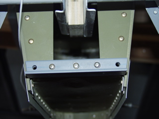
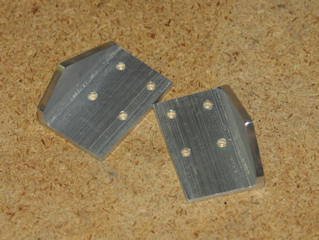
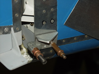
There is only one hole drilled in the fuselage. The rest of these holes are to be drilled "in assembly" to make sure they line up correctly. I clecoed the first hole and used an edge clamp to hold it in place. I didn't get to drill the remaining holes yet. I'll do that next time. |
 |
| |
|
5/20/05 - Empennage Fairing - 3 hours
The rudder stops are now in place, but in drilling one of the holes I inadvertently pushed the bulkhead flange away from the outer skin, which means the pop rivet can't engage both layers of skin. So now I have to figure out a way to get it pressed back against the skin. It's always something.
To fix this I will need to remove the empennage from the fuselage so I have better access into the rear of the fuselage. |
 |
| |
|
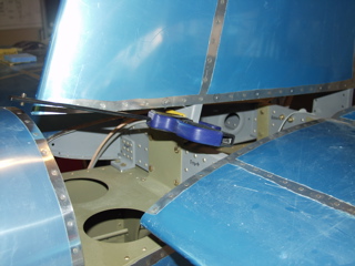
Before I do that, I decided to fit the empennage fairing. The instructions say to trim the fiberglass so there is 1/4" minimum clearance around the elevator horns. So, I trimmed and sanded incrementally until the fairing fit around the elevator horns.
There's lots more work to be done on this, but this is a good start, I believe. But today I've got bigger fish to fry. It's time to hang the engine. |
 |
| |
|
 |
 |
| |
|
| Next: The Texas RV Fly-In, and Avionics |
|
| |
|