| |
|
Previous: Electrical Part One |
|
| |
|
| If it seems like I'm taking a while to do the electrical stuff, it's because I keep running into things that I really need to do before running the wires. I'm in what seems to be an endless cycle of chicken-and-egg scenarios with regards to the electrical system, so I think you will continue to see non electrical things happening on these pages. |
| |
|
3/5/05 - Antennas - 5 hours
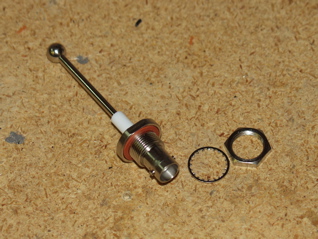
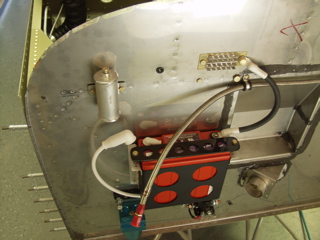
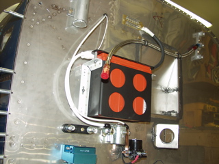
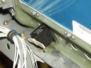
I tried to get some of the big items knocked off my list today, but just about as soon as I started, I ran across parts that I didn't have, or that I forgot to order. I intended to get all of the big electrical parts finished up on the engine side of the firewall, but all I was able to do was this diode. I then decided to take an inventory of the exact types and sizes of terminals that I still need, so I can place an order with B&C on Monday.
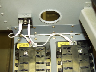
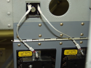
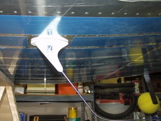
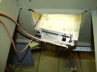
I did manage to wire the diode across the main bus and e-bus. I had to make these long enough to allow the trap door to be opened. Here it is, first closed, then open. |
 |
| |
|
 |
 |
| |
|
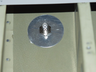
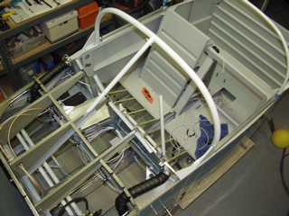
I decided to switch gears since I don't have the right parts to continue with the wiring. I have been planning to run the fattest wires first, and some of the fattest are the coaxial antenna wires. I first had to decide where to put the antennas, then I had to decide how to mount them. I am mounting the antennas in the bays underneath the seats, just about in line with the joint between the forward and aft seat floors.
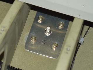
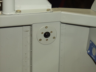
The transponder antenna was first and was also the easiest, since it installs with only one 1/2" hole. I mounted this one on the right side, and I made a doubler plate out of some round scrap. |
 |
| |
|
 |
 |
| |
|
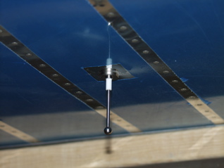
I've been a ham radio operator for a long time, and the rule of thumb is to make antenna connections as short as possible and put as few connectors in the feed line as you can get away with. Doing these things will reduce the amount of signal loss from the antenna to the radio and vice versa.
Next I tackled the com antenna. There are two ways to mount these antennas. One way is to not use a gasket and allow the antenna's base to contact the skin directly for the ground plane. The other way is to put the gasket between the antenna and the skin, and then add a doubler plate which helps the antenna screws make the connection to the ground plane. I went ahead and installed the gasket since it will hopefully keep moisture out of the connectors. Again, I made a doubler plate out of some scrap, and I spent quite a while on my back underneath the plane making sure the antenna was in trail and that the holes were drilled properly. |
 |
| |
|
 |
 |
| |
|
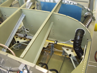
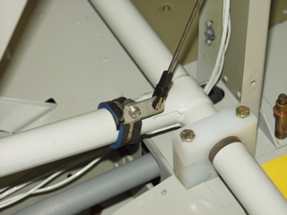
3/6/05 - Feed lines - 2 hours
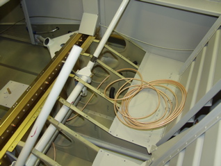
Now for some wiring fun. I decided to run the antenna wires through the seat ribs. I installed grommets in the 5/16" holes I drilled, and I secured the wire underneath the control rods with plastic clamps to keep them from interfering in any way with the control system. I pulled the coax up the left side of the center section, and I plan to run the intercom and other wiring along the right side. This should keep the radio signal from bleeding into the intercom, although I'm not really sure it would be an issue anyways. |
 |
| |
|
 |
 |
| |
|
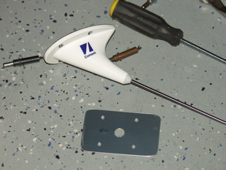
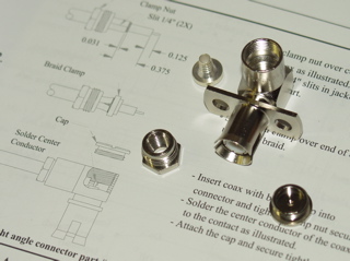
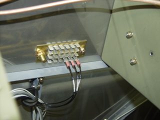
3/8/05 - Antenna connectors - 1 hour
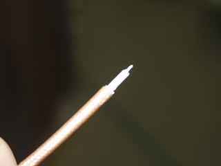
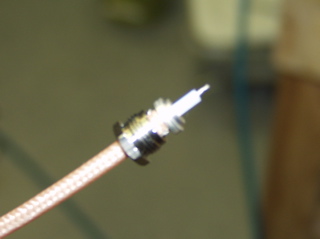
With the coax runs completed, it's time to install the connectors. The BNC connectors are pretty straightforward. I don't have one of those fancy strippers, so I have to do my best to estimate the lengths. Once it's stripped properly, it is a simple matter of crimping the center pin and then crimping the barrel. What wasn't so easy was this strange looking contraption that goes on the back of the SL-40. Sorry for the out of focus pictures, but here you can see the coax before and during assembly. |
 |
| |
|
 |
 |
| |
|
Fortunately for me, there is a step-by-step guide to assembling this connector in the installation manual for the SL-40.
The center conductor is soldered to the center post inside the connector. I pre-soldered the center conductor before I assembled it, so when it came to soldering the pin, all I had to do was to touch it with the iron and add a bit more solder to the joint. |
 |
| |
|
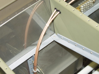
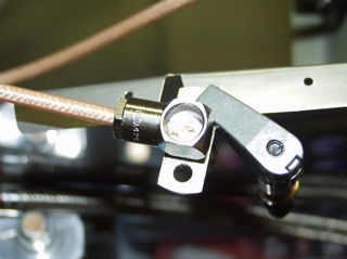
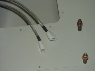
| Here is the results of my labor. The coax lines still need to be secured, and I left a service loop for each of these lines, not necessarily for ease of maintenance, but so that I can cut and add new connectors in the future if I ever decide to upgrade the radios. |
 |
| |
|
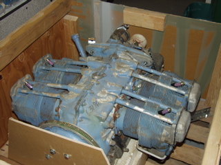
3/9/05 - Engine Shipping, RV-10 - 0 hours
Although I'm not considering build time per-se, I did build a crate for my engine so that I could ship it to AeroSport Power for an overhaul. I had toyed with the idea of doing the overhaul myself, but I got busy with real work, so I decided to go ahead and have someone else do it for me. When this engine returns to me it will be ready to bolt onto the fuselage!
The freight company showed up a day late due to a scheduling mixup, but it is finally on it's way to Canada. |
 |
| |
|
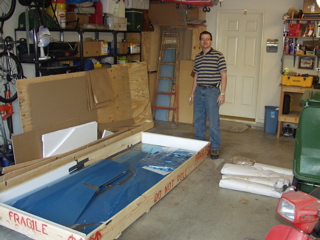
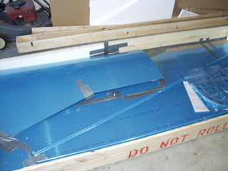
| My friend, Todd, received his RV-10 empcone kit today, so I buzzed by his house this evening to take a look. It looks a lot like my kit, but he tells me that he doesn't have an instruction book. The plans contain all of the instructions, which is pretty cool. The parts seem to be just "Biggie Sized" versions of my kit, although this kit also contains the tailcone part of the fuselage, so it's hard to make a good comparison. |
 |
| |
|
| I'm really looking forward to seeing how this kit goes together. I hope to eventually build one of these myself, so I am generously loaning tools to Todd in hopes that he'll share some of his experiences with me along the way. He's not a web guy like me, so he won't be doing an online construction log. That means he'll probably finish the plane a lot quicker! I'll try to grab some photos of his work along the way. |
 |
| |
|
3/10/05 - EAA Chapter Meeting - 0 hours
Tonight is EAA night, but I managed to squeeze in a couple hours of work on the electrical system before and after the meeting. By the way, I met Jim Smith at the meeting. He's another local builder who is just finishing up his empennage. He has a nice construction site as well. |
| |
|
3/11/05 - Finally some wiring! - 3 hours
Hey, I'm finally doing some electrical work!
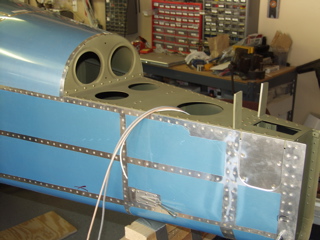
It's time to get the big wires run. here's a shot of the battery area after I drilled a little pass-through hole. |
 |
| |
|
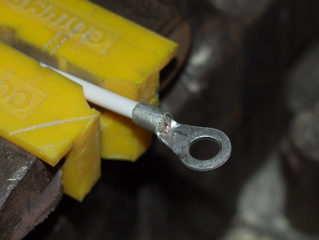
I soldered a ring terminal on the thick, 8awg wire that goes from the battery contactor to the main bus. Once again, I found the information provided by Bob Nuckolls at www.aeroelectric.com to be invaluable in figuring out what to do here.
This is a stiff cable that doesn't allow much flexibility, so I had to choose my routing carefully. You can see in the picture below that I ran the line through an adel clamp attached to the bottom of the panel support rib. It then passes through the big wire hole in the subpanel where it attaches to the main bus. |
 |
| |
|
 |
 |
| |
|
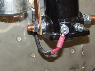
| On the firewall site, I tied the wire to the main battery line to keep everything organized . This line has to attach to the switched side of the battery contactor, which happens to be underneath the battery on the opposite side of the contactor. |
 |
| |
|
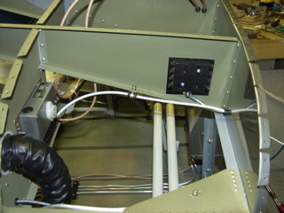
| The last thing I did was to attach the dimmer board to the subpanel. I placed this right next to the radio stack facing the instrument panel. This little device can handle up to 1.5 amps of lighting, so I hope to install a little terminal strip above it to organize the wires for the instruments that need to be dimmed. Honestly, I don't have that many instruments, so I don't know if this will be an issue or not. |
 |
| |
|
3/12/05 - Wiring - 11 hours
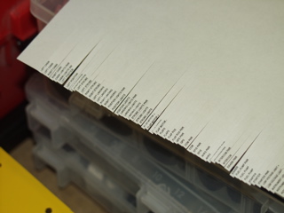
Today I had to drop one of my kids off for a spring break trip. He had to be at school at 5:15am, so when I returned home I decided I could take advantage of the extra hours to get busy on my wiring. I started by printing a bunch of labels on my printer so I could use Dan Checkoway's method of wire labeling. This involves using clear shrink tubing to enclose a paper label at both ends of each wire. Although it adds a lot of time to the process, I am convinced it will be worth it in the long run. |
 |
| |
|
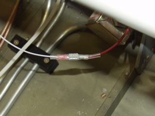
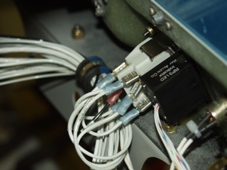
| The Facet fuel pump is pre-made with a fast-on connector, so I took advantage of this and used the same connector. I then shrink-wrapped the connection to keep it safely insulated, and to keep the connectors together. |
 |
| |
|
I decided that in order to keep the wiring runs organized, I should make a racetrack along the subpanel, with adel clamps serving to hold the wires in place. I put big thru-holes on either side of the instrument panel, similar to the one by the fuse blocks, where I can run wires to either the left or the right switch groups. In this way each switch group can be removed and worked on without a tangled mess of wires (hopefully.)
Right now I am just running the wires. I will attach the switches at a later time when I have them mounted to the switchplates. |
 |
| |
|
 |
 |
| |
|
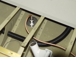
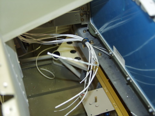
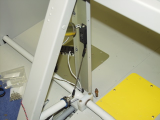
| The conduit I had previously installed worked perfectly as I ran the long runs back into the tail section. Here you can see the wires for the strobe, trim, and ELT antenna sticking out. When I install the empennage (hopefully soon) I will cut these wires to length. |
 |
| |
|
| It's hard to get an idea of the magnitude of all this wiring. Right now I have wires running all over the place. I'm just going down my list of items that need power, and running the correct gauge through the plane, trying to keep everything orderly. Eventually I will have to attach the wires to something, but right now all they get is a label. The only place I have attached connectors is at the fuse blocks. |
 |
| |
|
3/13/05 - More Wiring - 4 hours
I decided to at least try to put some connectors on some of the wires, so I started with the strobe wires. These require Mate-N-Lok connectors so they can plug into the strobe power supply. Unfortunately, the strobe kit only comes with three of these connectors, and I need at least eight since I plan to put connectors at the wing roots for easy attachment later. |
 |
| |
|
| In case you are wondering about the big fat wires, these are shielded three conductor wires that connect the strobes in the wings and tail to the strobe power supply. For consistency I have also run this type of wire to the switch on the instrumnet panel, hoping to keep strobe noise to a minimum. |
 |
| |
|
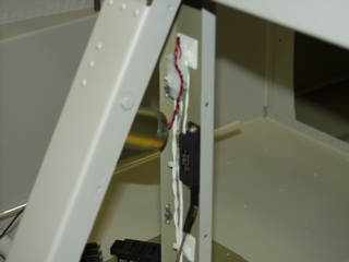
| I am planning to put some terminal blocks under the seats to facilitate the attachments of the trim servos to the stick grips and to route power to the position lights. Right now there are just lots of wires running through here. Eventually I will clean all this up, but I thought you might enjoy seeing a picture of what it's like during the process. |
 |
| |
|
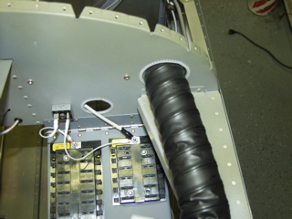
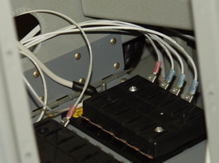
| Here is a closeup of the fuse blocks. The one with most of the wires so far is the main bus. Remember that this panel swings down, so I am making sure I have enough wire to allow it to travel easily. At least this picture shows something hooked up! |
 |
| |
|
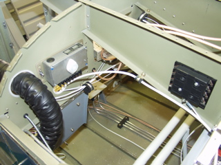
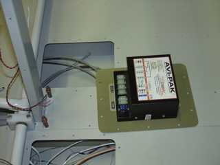
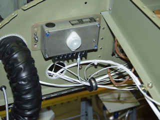
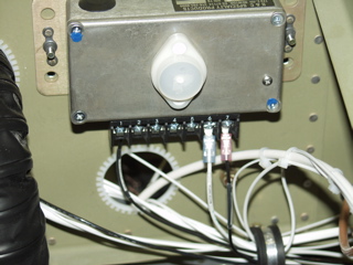
Finally, the regulator was causing some interference with the wires I was running to the fuse blocks, so I moved it up about 1 inch. This makes it easier to get the big, thick main battery wire into the hole, and allows enough flex so the battery trapdoor can swing down without incident.
This has been a long weekend of wiring. Some things I can't complete because I don't have the right parts, and other things I'm just delaying to later, but at least I can see some progress. |
 |
| |
|
3/14/05 - Dimpling - 1 hour
I promised Todd that he could use my c-frame, so since I had one skin left to dimple, I figured I better go ahead and do it before he comes asking for the tool! It is now dimpled and awaiting a coat of primer. I really don't need this skin yet, since it will cover up all the area I am currently wiring, but it will be good to have it ready to go at the proper time. |
| |
|
3/15/05 - Misc. Electrical - 2 hours
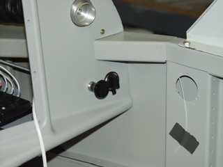
I went ahead and installed the auxiliary power outlet, also known as a cigarette lighter. This will allow me to power a variety of portable devices if necessary. I put it on the rightmost side of the panel. Hopefully in this location whatever is plugged into the outlet will not interfere with anything in flight. |
 |
| |
|
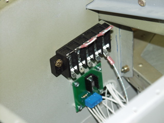
| Here's my instrument light dimmer block. This will allow me to connect multiple lights to the single dimmer control. This block is totally huge, but it's what I've got, so for the moment this is what I am using. |
 |
| |
|
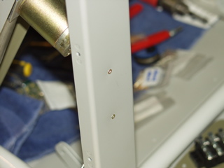
3/16/05 - More Misc Junk - 3 hours
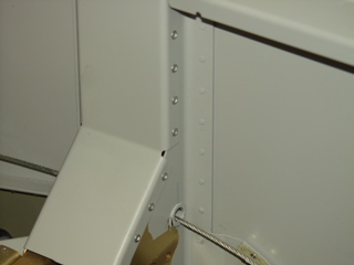
I have delayed installing these permanently because I wanted to make sure I could run the wires to the flood lights, but since I ran the wire the other day, there is nothing else keeping me from pop-riveting these little covers in place, so that's what I did.
The only issue I encountered was the uppermost rivets on the forward side. I can't seem to access them with the rivet squeezer I have. I am going to go look for one with a bit smaller profile in hopes of being able to access these last four rivets. |
 |
| |
|
| I received an order from Wicks today with a bunch of small miscellaneous hardware that I've been needing. In particular I had ordered some 4-40 screws, washers, and locknuts that I used to affix the eyeball flood light to my little homemade light plate. Now I can install my flood lights for good. The only thing left to do is to paint the screw heads, which I can do anytime I have the paint out. |
 |
| |
|
3/17/05 - Switchplates - 2 hours
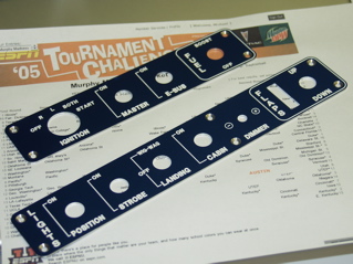
My switch plates came today, so between watching the NCAA tournament and doing some "real" work, I was able to get the first plate installed, and I got started on the second one.
These turned out really nice. It definitely makes mounting switches a snap. No alignment horrors to worry about. Just match-drill the thru-holes and insert the switches. |
 |
| |
|
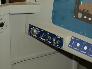
Here's the first one installed. This one includes the big fat key switch.
I have some lock washers on order which I will install behind the panel before I attach the switches permanently. |
 |
| |
|
3/18/05 - Flap Position Indicator - 2 hours
I have planned to install a Ray Allen position indicator on the instrument panel to display the status of the flaps. Attaching the indicator behind the panel can be done with screws, but I finally decided that I would use epoxy to attach the plastic case to the back of the composite instrument panel. You'll see soon what this looks like from the front.
To do this, I first removed the "guts" of the indicator. Next, I put epoxy on the case and on the panel. Finally, I used a rubber band stretched through the case to hold the case tightly to the panel.
I spent the rest of my time running some ground wires to the ground bus. |
 |
| |
|
 |
 |
| |
|
3/19/05 - Flap Position Sensor - 5 hours
Dan C. has a good idea for installing the flap position sensor, so I basically copied his technique. I went to the hobby shop and bought a threaded rod and a set of clevises. The threads are 4-40, and the clevises are just the right size to fit around the Ray Allen flap position sensor.
I spent a while running the flaps to the extreme limits of travel to determine the best location to attach the pushrod. I mounted the sensor to the back of the flap console using a pair of 4-40 flush head screws. |
 |
| |
|
 |
 |
| |
|
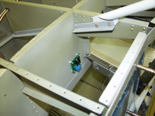
| Wiring this sensor was done with d-sub pins and sockets. I used a 2-circuit AMP connector to connect power to the flap motor. |
 |
| |
|
3/20/05 - Flap Wiring - 2 hours
I wanted to see if I could complete the flap control system today, so that's all I worked on. I attached the switch and ran power and ground to it. I also wired the position indicator to the sensor using the 5 conductor wire that the Ray Allen company sells. This all took a while to get right, but when I finally got power attached to it, everything worked great. The indicator runs up and down to match the flap position, just as it's supposed to. Sweet. |
 |
| |
|
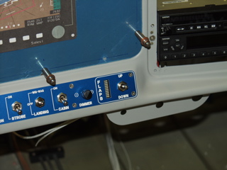
3/21/05 - Misc. Wiring - 2 hours
It's terrible when I can work for two hours and not have anything worth taking a picture of, but I did get some stuff accomplished. Mostly I spent my time labeling wires and running wires to the switches.
As promised, here is the front of the flap position indicator. It's located just to the left of the flap switch. Notice that it is recessed into the panel by about 1/4". Hopefully this will provide at least a little bit of a glare shield, although I think in direct sunlight it won't matter. |
 |
| |
|
| Next: Electrical Part Three |
|
| |
|