| |
|
Previous: Firewall Stuff |
|
| |
|
1/27/05 - Prepping for paint - 9 hours
I'm trying to wrap up some stuff today. I'd like to get the subpanel assembly permanently riveted, but it hasn't been dimpled yet. I started by reattaching the forward top skin and match-drilling the rivet holes. Next, I removed the skin and match-drilled the holes in the subpanel. This was all removed and deburred and dimpled. |
 |
| |
|
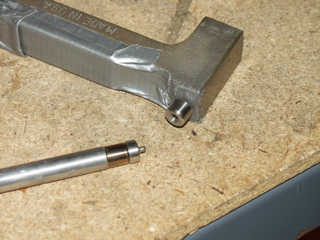
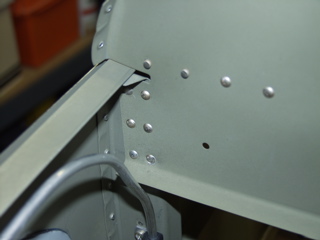
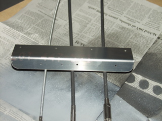
| I had to find a way to dimple the firewall where the ribs are attached. The picture at the right shows how I drilled a hole in a bucking bar to accept a dimple die. This bucking bar didn't work because there is a piece at the other end that interfered with the surface I was trying to dimple. So I did the same thing to another bucking bar. It worked pretty well, I guess. It's sort of disconcerting to be hammering on the firewall. |
 |
| |
|
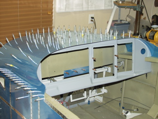
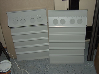
Here's me match-drilling the side covers to the 904 bulkhead. I used an angle drill for this. Afterwards I had to spend a while deburring and then cleaning all the metal shavings out of the plane (again.)
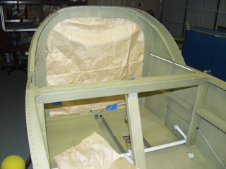
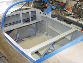
All this is in preparation for hopefully painting the interior this weekend. I went ahead and removed all of the covers and seat skins, and started the process of masking the places where I don't want paint. |
 |
| |
|
 |
 |
| |
|
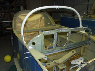
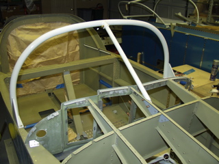
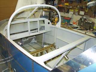
The one exception are the 904 bulkhead side covers, which I wanted to have pop-riveted in place before painting. It then occurred to me that the roll bar needs to be attached prior to riveting the sides, so I stopped masking and got busy mounting the roll bar.
Note: The following is not the correct way to mount the roll bar! I misread the instructions and although mine seems to have turned out fine, please follow the instructions and not this website. |
 |
| |
|
I started by doing a little bit of coercing to get the roll bar to have the correct edge distance on the canopy deck. This was done by placing the roll bar on the floor and applying pressure at the top center of the bar, which spread out the sides just a bit, which was all that I really needed.
Once the size was pretty close, I positioned the roll bar on the canopy deck. Next, I located the spacer blocks provided in the kit, and made the appropriate adjustments to each, making sure I had both a left set and a right set. |
 |
| |
|
 |
 |
| |
|
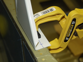
This is where I went wrong. The instructions say to lay out and drill #40 holes. I should have done this with the roll bar off the plane, but I didn't. Instead, I painstakingly positioned, clamped, and then marked the flange of the roll bar. In hindsight it is obvious to me what Vans wants you to do, but I totally misread the instructions, so I did it wrong.
Anyways, I carefully drilled #40 holes through the roll bar flange and into the canopy deck. Then I moved to the other side and after verifying the position and measuring the distance, did it again. |
 |
| |
|
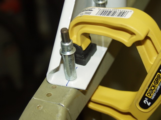
The result was that I had the roll bar clecoed in place with #40 clecoes.
This is about the time I realized what Vans wanted me to do, but obviously it was too late. So, I commenced to removing the rollbar from the plane. I went ahead and positioned and drilled the spacer blocks, and then moved them to the drill press to enlarge the holes.
Then I picked back up with the instructions, enlarging the holes in the flange and the deck, with the #12 hole forward, and the 1/4" hole aft, just like the plans. |
 |
| |
|
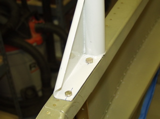
There is some extra material that can be removed from the flange, so I went ahead and used my die grinder to chop off the excess.
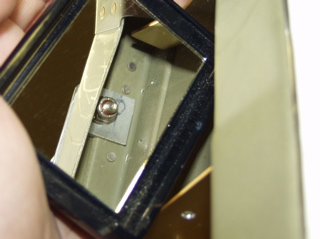
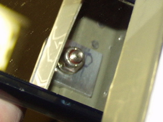
Installing the bolts was quite a challenge. The forward one is fairly easy to do, since the access is better. The aft bolt is a pain because the bottom of the canopy deck wraps around, so you only have about 3/4" of space to work. I used a box wrench to hold the nut, and then I tightened the bolt.
Below are a couple of "mirror shots" of the easy bolt. I couldn't even get a picture of the hard bolt! |
 |
| |
|
 |
 |
| |
|
So, after all that fuss I now have the roll bar installed. Now what was I doing before I got sidetracked? Oh yeah, I was going to assemble the subpanel assembly... :-(
Maybe tomorrow. |
 |
| |
|
1/28/05 - Electrical Planning - 2 hours
I spent a while with the electrical system design. Design is probably too strong of a word. More appropriately I should say that I am organizing the electrical system of the plane. The hard stuff has already been figured out by folks like Bob Nuckolls. I am just following in the footsteps of many other builders. Right now I am organizing the wiring and making sure I have adequate circuit protection. |
| |
|
1/29/05 - Subpanel - 6 hours
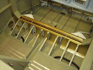
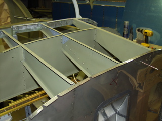
Back to the plane. I finally got the subpanel and panel support ribs riveted in place. The rivets were not easy, especially in the corners. I had to use several bucking bars and an offset rivet set, but eventually I was successful. I made some more dents in the firewall. It seems that I can't do anything with the firewall without making it look worse. I guess it doesn't really matter since you won't be able to see it once the engine is installed. It still bugs me that I can't seem to rivet the stainless steel with any sort of regularity. |
 |
| |
|
 |
 |
| |
|
I installed the transducer manifold. At the moment I can't tell you what this is for, but it says to install it here, so I did.
That's the cool thing about building an RV. You start with maybe a limited amount of knowledge about an airplane and its systems, and one day at a time you are exposed to new systems and words and technologies. If I tried to understand it all at once it would be like drinking from a fire hose. But instead I follow the instructions and do my planning and slowly I learn what it takes to finish the plane. |
 |
| |
|
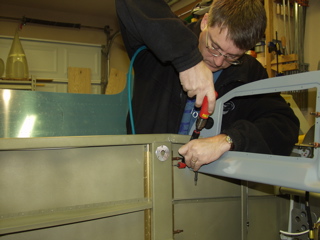
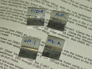
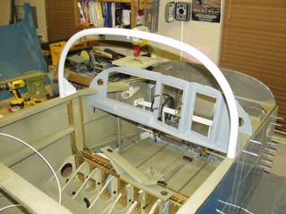
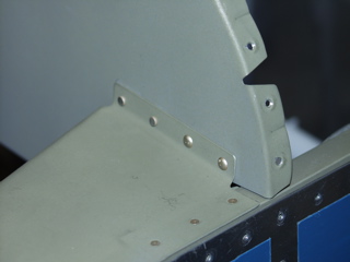
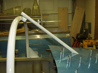
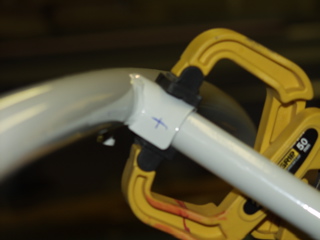
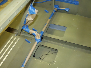
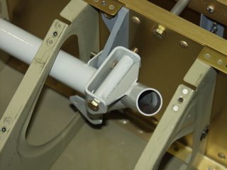
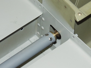
Now that the support ribs are installed I can install the reinforcement bar to the rollbar. First I test-fit it and made a mark on the bar where I thought it needed to be cut. I only had to trim it twice before it was the right length.
Next I marked the attach point on the rollbar and carefully drilled the holes through both the rollbar and the reinforcement bar.
Also, I had to clean up some of the welds around the base of the bar because they kept it from sitting flush with the skin. |
 |
| |
|
 |
 |
| |
|
 |
 |
| |
|
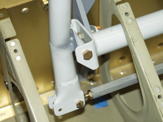
| Here it is, temporarily bolted in place. |
 |
| |
|
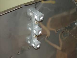
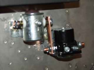
| One last thing for the day, as well as a question. I fabricated the copper bars that attach the master contactor and the starter solenoid. My question is this: the electrical attach points have split lock washers, rather than locknuts. Should they be safetied in any way (with threadlocker or whatever) to make sure they don't inadvertently loosen? This is on the engine side of the firewall, so temperature will be an issue. I need to figure this out. |
 |
| |
|
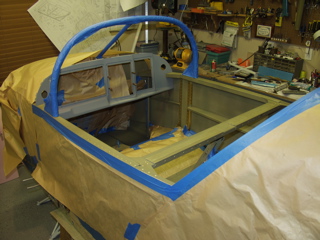
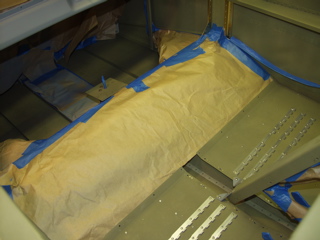
1/30/05 - Masking - 2 hours
Look, a paper airplane!
In preparation for painting the cabin area, I masked off everything that I didn't want to paint. This included the firewall, the powdercoat parts, flap motor and the control cables.
|
 |
| |
|
 |
 |
| |
|
1/31/05 - Nothing, it's freezing - 0 hours
I've got the cabin all ready for paint, but it's cold and rainy with a chance of snow, so I'm going to have to postpone the paint for a day or two. |
| |
|
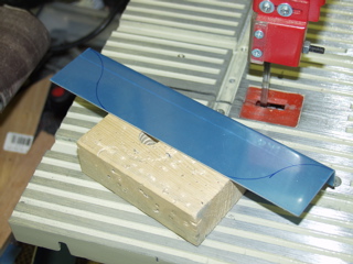
2/2/05 - Throttle Bracket - 2 hours
It's still too cold to paint, but apparently not too cold for me to freeze my butt off working on aluminum. It just doesn't feel right to not get anything done on the plane, so I went out and found something else that needed doing. I settled on the throttle bracket. I wanted to get this painted when I painted everything else anyways, so it is good that I'm getting it done.
I started by tracing some cutlines onto the bracket hoping to soften the edges a bit. |
 |
| |
|
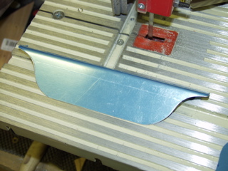
| I cut it using the bandsaw, which isn't really good for tight turns but these were gentle enough that it worked out okay. I then used the scotchbrite wheel and my die grinder to finish up. It took me a while to make both sides the same. I had a paper template that I used to test-fit both sides until I got them the same. This probably won't be noticable to anyone, but I didn't want it looking goofy. |
 |
| |
|
| Next came the hole-drilling. I couldn't figure out the correct spacing, so I got out the throttle, mixture, and carb heat controls from the firewall forward kit. After messing around for a while I settled on putting the throttle directly in the center and offsetting the mixture 2.75" to the right and the carb heat 2.25" to the left. This made the whole thing look and feel more balanced as the carb heat knob is much smaller than the other two. I hope I like it this way. This isn't probably something I'm going to want to change later on since the cables go in from the front and attach on the other side of the firewall! |
 |
| |
|
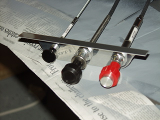
After settling on the positions I was able to drill the holes in the second bracket. These holes are for the Adel clamps that will hold the cables up and away from the floor.
After I finished working out these details and priming the parts, I still had some time available. I was looking for something I could do inside the house, so I started messing with the wingtip lights, thinking that I could do some soldering. The trouble is that before I can solder I had to do a bunch of shaping and cutting, so I spent the rest of the evening working on the lights. |
 |
| |
|
2/3/05 - Paint - 3 hours
The sun finally came out for a while, so I dragged out all of the parts that I could get outside and I threw brown paper over all of my workbenches in the garage. I'm using JetFlex for the interior. It is a water based aircraft paint and it really worked well. I'm not a painter, and my only experience with the spray gun is the primer I've been shooting on everything. This is really just a base coat that won't be seen because of the fabric interior, but I still wanted to do a good job on it. I'm happy with the results. |
 |
| |
|
 |
 |
| |
|
 |
 |
| |
|
| Afterwards I spent more time working on the lights. |
| |
|
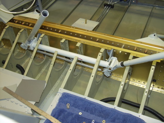
2/5/05 - Control sticks - 1 hour
Most of the day was taken up with the wingtip lights, but they are now finished! I did manage to start installing the control sticks.
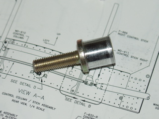
I need to find out if the top bolt needs to be installed with the nut on the aft side as it shows on the plans or if it can be installed as I have it below. If I have to install it from the front I will need to remove the bracket. |
 |
| |
|
 |
 |
| |
|
2/11/05 - Elevator pushrod - 4 hours
This has not been a good week for working on the plane. Last night was the monthly EAA meeting, but today (Friday) I decided to take a little while off from work and mess with the plane. The paint has had plenty of time to cure, so now it's time to get back to the grindstone.
I had previously called to check on the direction for the bolt mentioned above, and indeed the preview plans are wrong. The big plan set shows the bolt inserted from the rear, as I sort of expected. |
| |
|
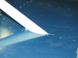
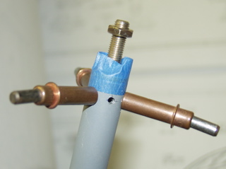
I had previously cut the forward elevator pushrod to length, so today I started assembling it. I went ahead and primered the inside (and the outside) of the pushrod.
I found out quickly that the threaded insert wouldn't fit into the tube. After messing around, I figured out that there was a slight lip on the bottom of the insert. So I chucked it into the drill press and filed it smooth. |
 |
| |
|
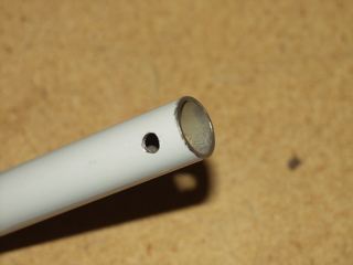
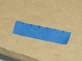
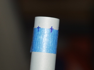
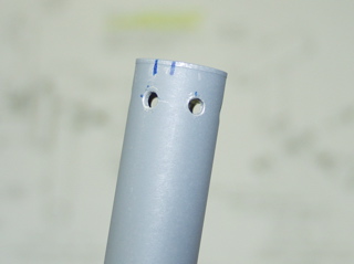
Next I had to drill six evenly spaced holes around the tube. The process is to wrap a piece of tape (or paper) around the tube and mark the location where it overlaps. This measures the circumference of the tube. Then you take the tape off the tube and divide it into equal parts, making a mark at each location where a hole should be drilled. The next thing is to put the tape back on the tube and mark the tube.
With the threaded insert temporarily taped in place, I drilled holes where I had marked. |
 |
| |
|
 |
 |
| |
|
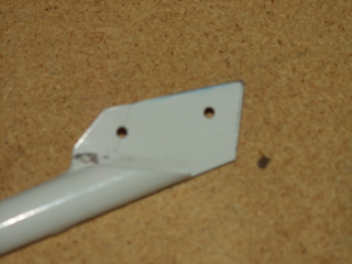
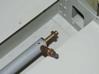
I went ahead and marked the tube and the insert so that I could get them back together later on, then I removed the ends.
One trick I learned by reading other builder sites is that the elevator pushrod will not fit if you assemble it, so I took the ends off and inserted the pushrod. Then I reattached the tips and clecoed them to the tube. |
 |
| |
|
 |
 |
| |
|
| Here is the pushrod with the pop rivets installed. |
 |
| |
|
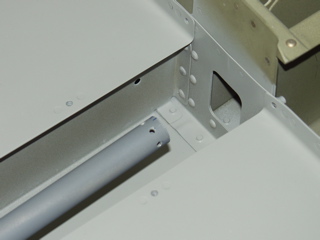
Next I worked (for a long time) on getting the right washers installed to make sure the control stick moved smoothly. I had to get into the plane and fiddle with the bellcrank for a while, but I finally got the pushrod properly connected to the bellcrank.
Next: Slider Canopy |
 |
| |
|